
User Guide

44
Design Guide - HZH/HZV Series
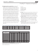
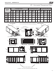
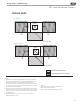
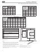
HZ - Horizontal Dimensional Data
Horizontal
Model
Overall Cabinet
*A
Width
B
Length
C
Height
024
in
cm
22.4
56.8
62.2
158.0
19.3
48.9
036
in
cm
25.4
64.5
71.2
180.8
21.3
54.0
048
in
cm
25.4
64.5
76.2
193.5
21.3
54.0
060 &
070
in
cm
25.4
64.5
81.2
206.2
21.3
54.0
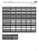
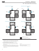
Horizontal
Model
Water Connections
1 2 3 4 5
Loop
In
D
Loop
Out
E
HWG
In
F
HWG
Out
G
Cond.
H
Water
Loop
FPT
HWG
FPT
024
in
cm
3.9
9.9
8.4
21.3
13.9
35.2
16.9
42.9
3.5
8.9
3/4” 1/2”
036
in
cm
3.9
9.9
8.4
21.3
15.6
39.7
18.9
47.9
3.4
8.6
3/4” 1/2”
048
in
cm
3.9
9.9
8.4
21.3
15.6
39.7
18.9
47.9
3.4
8.6
1” 1/2”
060 &
070
in
cm
3.9
9.9
8.4
21.3
15.6
39.7
18.9
47.9
3.4
8.6
1” 1/2”
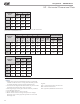
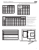
Horizontal
Model
Electrical Knockouts
J
1/2”
K
1/2”
L
3/4”
Low
Voltage
External
Pump
Power
Supply
024
in
cm
3.6
9.2
6.1
15.6
8.6
21.9
036
in
cm
3.6
9.2
6.1
15.6
8.6
21.9
048
in
cm
3.6
9.2
6.1
15.6
8.6
21.9
060 &
070
in
cm
3.6
9.2
6.1
15.6
8.6
21.9
*Does not include air lter supports. Add 2” (5.1cm) when a 1” (25.4mm) lter is used, add 3”
(7.6cm) when a 2” (50.8mm) lter is used.
Notes:
1. While clear access to all removable panels is not required,
installer should take care to comply with all building codes
and allow adequate clearance for future eld service.
2. Horizontal units shipped with lter bracket only. This bracket
should be removed for return duct connection
3. Discharge ange and hanger brackets are factory installed.
4. Condensate is 3/4” FPT.
5. CCP and BSP requires 2’ service access.
6. Blower service access is through back panel on straight
discharge units or through panel opposite air coil on back
discharge units.
Legend:
CCP = Control/Compressor Access Panel
BSP = Blower Service Panel
ASP = (Optional) Additional Service Panel
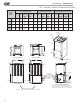
Water Connections -
Units with ClimaDry
®
1 2
Loop
In D
Loop
Out E
2.1
5.2
10.0
25.4
6.01
15.1
13.1
33.4
6.01
15.1
13.1
33.4
6.01
15.1
13.1
33.4