Design Guide HZH/V Series www.marsdelivers.
Table of Contents HZ Premier Efficiency Series Unit Features iGate Communicating Controls ® vFlow Internal Variable Water Flow Control Selection Procedure HZ Series Nomenclature Performance Data AHRI/ASHRAE/ISO 13256-1 Performance Data Selection Notes - vFlowTM Models Performance Data – HZ H/V/D 024 (Part Load), No vFlow® Performance Data – HZ H/V/D 024 (Part Load), No vFlow® Performance Data – HZ H/V/D 036 (Part Load), No vFlow® Performance Data – HZ H/V/D 036 (Full Load), No vFlow® Performance Data – HZ
Table of Contents HZ Premier Efficiency Series HZ - Horizontal Dimensional Data HZ - Horizontal Service Access HZ - Vertical Upflow Dimensional Data HZ - Vertical Service Access HZ - Vertical Downflow Dimensional Data Corner Weights Electrical Data HZ Series Wiring Diagram Matrix Typical Wiring Diagram – Single Phase HZ Units with Modulating Water Valve Typical Wiring Diagram – Single Phase 208/230V HZ Units with Variable Pump Typical Wiring Diagram – Single Phase HZ Units with MWV and MPC Controller Typic
Design Guide - HZH/HZV Series Unit Features THE HZ SERIES As one of the highest efficiency water-source heat pump on the planet, the HZ Series raises the bar for water-source heat pump efficiencies, features and application flexibility. Not only does the HZ Series far exceed ASHRAE 90.1 efficiencies, but it also uses EarthPure® (HFC-410A) zero ozone depletion refrigerant, making it an extremely environmentallyfriendly option.
Design Guide - HZH/HZV Series Unit Features UNIT FEATURES • Sizes 024 (2 ton, 7.0 kW) through 070 (6 tons, 19.3 kW) • EarthPure® (HFC-410A) refrigerant • Copeland UltraTech™ two-stage unloading scroll compressors • ECM variable speed communicating fan motor with soft start • Exceeds ASHRAE 90.
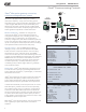
Design Guide - HZH/HZV Series iGate® Communicating Controls iGate® Information gateway to monitor, control and diagnose your system HZ Series is equipped with industry-first, iGate – Information Gateway – 2-way communicating system that allows users to interact with their geothermal system in plain English AND delivers improved reliability and efficiency by precisely controlling smart variable speed components. iGate® makes Tranquility® Digital series the easiest geothermal products to install and service.
Design Guide - HZH/HZV Series vFlow® Internal Variable Water Flow Control vFlow® Internal Variable Water Flow Industry-first, Built-in vFlow® provide an ultra-highefficient, variable speed, internal water flow system. It saves installers time and labor by avoiding installing bulky external pumps, valves, or flow regulators. Multi-unit installations are also much simpler with vFlow® systems, as the units automatically adjust water flow across the system.
Design Guide - HZH/HZV Series Selection Procedure Reference Calculations Heating Cooling HE LWT = EWT GPM x 500 LAT = EAT + HC CFM x1.08 LWT = EWT + HR GPM x 500 LAT (DB) = EAT (DB) - LC = TC - SC SC CFM x1.
Design Guide - HZH/HZV Series Selection Procedure Step 1 Determine the actual heating and cooling loads at the desired dry bulb and wet bulb conditions. Step 2 Obtain the following design parameters: Entering water temperature, water flow rate in GPM, air flow in CFM, water flow pressure drop and design wet and dry bulb temperatures. Air flow CFM should be between 300 and 450 CFM per ton. Unit water pressure drop should be kept as close as possible to each other to make water balancing easier.
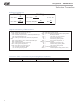
Submittal Data - HZ Series Design Guide - HZH/HZV Series TE Series Nomenclature HZ Series Nomenclature NOTES: 1. Residential class units come standard w/75 VA transformer stainless steel drain pan, ECM motor, and two stage scroll compressors. Units are painted polar ice. 2. Flow controller comes standard with variable speed pump, flushing valves, and expansion tank. Internal flow controller is only available when digit 12 option is selected for copper coax. 3. Motorized valve is two way modulating.
Design Guide - HZH/HZV Series Performance Data AHRI/ASHRAE/ISO 13256-1 ASHRAE/AHRI/ISO 13256-1. English (I-P) Units Water Loop Heat Pump Model Cooling 86°F Ground Water Heat Pump Heating 68°F Cooling 59°F Ground Loop Heat Pump Heating 50°F Full Cool 77°F Part Cool 68°F Capacity Btuh EER Btuh/W Capacity Btuh COP Capacity Btuh EER Btuh/W Capacity Btuh COP Capacity EER Btuh Btuh/W HZ024 Part 19,200 19.8 23,600 7.0 22,000 34.1 19,000 5.
Design Guide - HZH/HZV Series Performance Data Selection Notes - vFlow® Models Operation in Shaded Area: Closed Loop Application Antifreeze use recommended in this range. Also Clip JW3 on DXM2 board. For operation in the shaded area, appropriate levels of a proper antifreeze should be used in systems with leaving water temperatures of 40°F or below and the JW3 jumper should be clipped. This is due to the potential of the GPM refrigerant temperature being as low as 32°F [0°C] with 40°F [4.
Design Guide - HZH/HZV Series Performance Data – HZ H/V/D 024 (Part Load), No vFlow® 850 CFM Nominal (Rated) Airflow Heating, 750 CFM Nominal (Rated) Airflow Cooling Performance capacities shown in thousands of Btuh EWT °F 20 30 40 50 60 70 80 85 90 100 110 120 GPM 4.5 4.5 2.3 2.3 3.4 3.4 4.5 4.5 2.3 2.3 3.4 3.4 4.5 4.5 2.3 2.3 3.4 3.4 4.5 4.5 2.3 2.3 3.4 3.4 4.5 4.5 2.3 2.3 3.4 3.4 4.5 4.5 2.3 2.3 3.4 3.4 4.5 4.5 2.3 2.3 3.4 3.4 4.5 4.5 2.3 2.3 3.4 3.4 4.5 4.5 2.3 2.3 3.4 3.4 4.5 4.5 2.3 2.
Design Guide - HZH/HZV Series Performance Data – HZ H/V/D 024 (Full Load), No vFlow® 950 CFM Nominal (Rated) Airflow Heating, 850 CFM Nominal (Rated) Airflow Cooling Performance capacities shown in thousands of Btuh EWT °F 20 30 40 50 60 70 80 85 90 100 110 120 GPM 6.0 6.0 3.0 3.0 4.5 4.5 6.0 6.0 3.0 3.0 4.5 4.5 6.0 6.0 3.0 3.0 4.5 4.5 6.0 6.0 3.0 3.0 4.5 4.5 6.0 6.0 3.0 3.0 4.5 4.5 6.0 6.0 3.0 3.0 4.5 4.5 6.0 6.0 3.0 3.0 4.5 4.5 6.0 6.0 3.0 3.0 4.5 4.5 6.0 6.0 3.0 3.0 4.5 4.5 6.0 6.0 3.0 3.
Design Guide - HZH/HZV Series Performance Data – HZ H/V/D 036 (Part Load), No vFlow® 1000 CFM Nominal (Rated) Airflow Heating, 1000 CFM Nominal (Rated) Airflow Cooling Performance capacities shown in thousands of Btuh EWT °F 20 30 40 50 60 70 80 85 90 100 110 120 GPM 6.0 6.0 3.0 3.0 4.5 4.5 6.0 6.0 3.0 3.0 4.5 4.5 6.0 6.0 3.0 3.0 4.5 4.5 6.0 6.0 3.0 3.0 4.5 4.5 6.0 6.0 3.0 3.0 4.5 4.5 6.0 6.0 3.0 3.0 4.5 4.5 6.0 6.0 3.0 3.0 4.5 4.5 6.0 6.0 3.0 3.0 4.5 4.5 6.0 6.0 3.0 3.0 4.5 4.5 6.0 6.0 3.0 3.
Design Guide - HZH/HZV Series Performance Data – HZ H/V/D 036 (Full Load), No vFlow® 1250 CFM Nominal (Rated) Airflow Heating, 1250 CFM Nominal (Rated) Airflow Cooling Performance capacities shown in thousands of Btuh EWT °F 20 30 40 50 60 70 80 85 90 100 110 120 GPM 9.0 9.0 4.5 4.5 6.8 6.8 9.0 9.0 4.5 4.5 6.8 6.8 9.0 9.0 4.5 4.5 6.8 6.8 9.0 9.0 4.5 4.5 6.8 6.8 9.0 9.0 4.5 4.5 6.8 6.8 9.0 9.0 4.5 4.5 6.8 6.8 9.0 9.0 4.5 4.5 6.8 6.8 9.0 9.0 4.5 4.5 6.8 6.8 9.0 9.0 4.5 4.5 6.8 6.8 9.0 9.0 4.5 4.
Design Guide - HZH/HZV Series Performance Data – HZ H/V/D 048 (Part Load), No vFlow® 1350 CFM Nominal (Rated) Airflow Heating, 1350 CFM Nominal (Rated) Airflow Cooling Performance capacities shown in thousands of Btuh EWT °F 20 30 40 50 60 70 80 85 90 100 110 120 GPM 9.0 9.0 4.5 4.5 6.8 6.8 9.0 9.0 4.5 4.5 6.8 6.8 9.0 9.0 4.5 4.5 6.8 6.8 9.0 9.0 4.5 4.5 6.8 6.8 9.0 9.0 4.5 4.5 6.8 6.8 9.0 9.0 4.5 4.5 6.8 6.8 9.0 9.0 4.5 4.5 6.8 6.8 9.0 9.0 4.5 4.5 6.8 6.8 9.0 9.0 4.5 4.5 6.8 6.8 9.0 9.0 4.5 4.
Design Guide - HZH/HZV Series Performance Data – HZ H/V/D 048 (Full Load), No vFlow® 1650 CFM Nominal (Rated) Airflow Heating, 1550 CFM Nominal (Rated) Airflow Cooling Performance capacities shown in thousands of Btuh EWT °F 20 30 40 50 60 70 80 85 90 100 110 120 GPM 12.0 12.0 6.0 6.0 9.0 9.0 12.0 12.0 6.0 6.0 9.0 9.0 12.0 12.0 6.0 6.0 9.0 9.0 12.0 12.0 6.0 6.0 9.0 9.0 12.0 12.0 6.0 6.0 9.0 9.0 12.0 12.0 6.0 6.0 9.0 9.0 12.0 12.0 6.0 6.0 9.0 9.0 12.0 12.0 6.0 6.0 9.0 9.0 12.0 12.0 6.0 6.0 9.
Design Guide - HZH/HZV Series Performance Data – HZ H/V/D 060 (Part Load), No vFlow® 1650 CFM Nominal (Rated) Airflow Heating, 1500 CFM Nominal (Rated) Airflow Cooling Performance capacities shown in thousands of Btuh EWT °F 20 30 40 50 60 70 80 85 90 100 110 120 GPM 12.0 12.0 6.0 6.0 9.0 9.0 12.0 12.0 6.0 6.0 9.0 9.0 12.0 12.0 6.0 6.0 9.0 9.0 12.0 12.0 6.0 6.0 9.0 9.0 12.0 12.0 6.0 6.0 9.0 9.0 12.0 12.0 6.0 6.0 9.0 9.0 12.0 12.0 6.0 6.0 9.0 9.0 12.0 12.0 6.0 6.0 9.0 9.0 12.0 12.0 6.0 6.0 9.
Design Guide - HZH/HZV Series Performance Data – HZ H/V/D 060 (Full Load), No vFlow® 2050 CFM Nominal (Rated) Airflow Heating, 1850 CFM Nominal (Rated) Airflow Cooling Performance capacities shown in thousands of Btuh EWT °F 20 30 40 50 60 70 80 85 90 100 110 120 GPM 15.0 15.0 7.5 7.5 11.3 11.3 15.0 15.0 7.5 7.5 11.3 11.3 15.0 15.0 7.5 7.5 11.3 11.3 15.0 15.0 7.5 7.5 11.3 11.3 15.0 15.0 7.5 7.5 11.3 11.3 15.0 15.0 7.5 7.5 11.3 11.3 15.0 15.0 7.5 7.5 11.3 11.3 15.0 15.0 7.5 7.5 11.3 11.3 15.
Design Guide - HZH/HZV Series Performance Data – HZ H/V/D 070 (Part Load), No vFlow® 1650 CFM Nominal (Rated) Airflow Heating, 1550 CFM Nominal (Rated) Airflow Cooling Performance capacities shown in thousands of Btuh EWT °F 20 30 40 50 60 70 80 85 90 100 110 120 GPM 14.0 14.0 7.0 7.0 10.5 10.5 14.0 14.0 7.0 7.0 10.5 10.5 14.0 14.0 7.0 7.0 10.5 10.5 14.0 14.0 7.0 7.0 10.5 10.5 14.0 14.0 7.0 7.0 10.5 10.5 14.0 14.0 7.0 7.0 10.5 10.5 14.0 14.0 7.0 7.0 10.5 10.5 14.0 14.0 7.0 7.0 10.5 10.5 14.
Design Guide - HZH/HZV Series Performance Data – HZ H/V/D 070 (Full Load), No vFlow® 2050 CFM Nominal (Rated) Airflow Heating, 1850 CFM Nominal (Rated) Airflow Cooling Performance capacities shown in thousands of Btuh EWT °F 20 30 40 50 60 70 80 85 90 100 110 120 GPM 17.0 17.0 8.5 8.5 12.8 12.8 17.0 17.0 8.5 8.5 12.8 12.8 17.0 17.0 8.5 8.5 12.8 12.8 17.0 17.0 8.5 8.5 12.8 12.8 17.0 17.0 8.5 8.5 12.8 12.8 17.0 17.0 8.5 8.5 12.8 12.8 17.0 17.0 8.5 8.5 12.8 12.8 17.0 17.0 8.5 8.5 12.8 12.8 17.
Design Guide - HZH/HZV Series Performance Data – HZ H/V/D 024 (Part Load), With vFlow® 850 CFM Nominal (Rated) Airflow Heating, 750 CFM Nominal (Rated) Airflow Cooling Performance capacities shown in thousands of Btuh EWT °F 20 30 40 50 60 70 80 90 100 110 120 GPM 1.0 1.0 1.3 1.3 1.3 1.3 1.3 1.3 1.7 1.7 1.7 1.7 1.7 1.7 2.3 2.3 2.5 2.6 2.5 2.6 2.3 2.3 3.4 3.4 4.5 4.5 2.3 2.3 3.4 3.4 4.5 4.5 2.3 2.3 3.4 3.4 4.5 4.5 2.3 2.3 3.4 3.4 4.5 4.5 2.3 2.3 3.4 3.4 4.5 4.5 2.3 2.3 3.4 3.4 4.5 4.5 2.3 2.
Design Guide - HZH/HZV Series Performance Data – HZ H/V/D 024 (Full Load), With vFlow® 950 CFM Nominal (Rated) Airflow Heating, 850 CFM Nominal (Rated) Airflow Cooling Performance capacities shown in thousands of Btuh EWT °F 20 30 40 50 60 70 80 90 100 110 120 GPM 1.3 1.4 1.7 1.7 1.7 1.7 1.7 1.7 2.2 2.3 2.2 2.3 2.2 2.3 3.0 3.0 3.3 3.4 3.3 3.4 3.0 3.0 4.5 4.5 6.0 6.0 3.0 3.0 4.5 4.5 6.0 6.0 3.0 3.0 4.5 4.5 6.0 6.0 3.0 3.0 4.5 4.5 6.0 6.0 3.0 3.0 4.5 4.5 6.0 6.0 3.0 3.0 4.5 4.5 6.0 6.0 3.0 3.0 4.
Design Guide - HZH/HZV Series Performance Data – HZ H/V/D 036 (Part Load), With vFlow® 1000 CFM Nominal (Rated) Airflow Heating, 1000 CFM Nominal (Rated) Airflow Cooling Performance capacities shown in thousands of Btuh EWT °F 20 30 40 50 60 70 80 90 100 110 120 GPM 1.5 1.5 1.8 1.8 1.8 1.8 1.8 1.8 2.4 2.5 2.4 2.5 2.4 2.5 3.0 3.0 3.6 3.7 3.6 3.7 3.0 3.0 4.5 4.5 6.0 6.0 3.0 3.0 4.5 4.5 6.0 6.0 3.0 3.0 4.5 4.5 6.0 6.0 3.0 3.0 4.5 4.5 6.0 6.0 3.0 3.0 4.5 4.5 6.0 6.0 3.0 3.0 4.5 4.5 6.0 6.0 3.0 3.
Design Guide - HZH/HZV Series Performance Data – HZ H/V/D 036 (Full Load), With vFlow® 1250 CFM Nominal (Rated) Airflow Heating, 1250 CFM Nominal (Rated) Airflow Cooling Performance capacities shown in thousands of Btuh EWT °F 20 30 40 50 60 70 80 90 100 110 120 GPM 2.0 2.0 2.5 2.5 2.5 2.5 2.5 2.5 3.3 3.4 3.3 3.4 3.3 3.4 4.5 4.5 5.0 5.1 5.0 5.1 4.5 4.5 6.8 6.8 9.0 9.0 4.5 4.5 6.8 6.8 9.0 9.0 4.5 4.5 6.8 6.8 9.0 9.0 4.5 4.5 6.8 6.8 9.0 9.0 4.5 4.5 6.8 6.8 9.0 9.0 4.5 4.5 6.8 6.8 9.0 9.0 4.5 4.
Design Guide - HZH/HZV Series Performance Data – HZ H/V/D 048 (Part Load), With vFlow® 1350 CFM Nominal (Rated) Airflow Heating, 1350 CFM Nominal (Rated) Airflow Cooling Performance capacities shown in thousands of Btuh EWT °F 20 30 40 50 60 70 80 90 100 110 120 GPM 1.8 1.9 2.3 2.4 2.3 2.4 2.3 2.4 3.1 3.1 3.1 3.1 3.1 3.1 4.5 4.5 4.6 4.7 4.6 4.7 4.5 4.5 6.8 6.8 9.0 9.0 4.5 4.5 6.8 6.8 9.0 9.0 4.5 4.5 6.8 6.8 9.0 9.0 4.5 4.5 6.8 6.8 9.0 9.0 4.5 4.5 6.8 6.8 9.0 9.0 4.5 4.5 6.8 6.8 9.0 9.0 4.5 4.
Design Guide - HZH/HZV Series Performance Data – HZ H/V/D 048 (Full Load), With vFlow® 1650 CFM Nominal (Rated) Airflow Heating, 1550 CFM Nominal (Rated) Airflow Cooling Performance capacities shown in thousands of Btuh EWT °F 20 30 40 50 60 70 80 90 100 110 120 GPM 2.5 2.5 3.1 3.1 3.1 3.1 3.1 3.1 4.1 4.2 4.1 4.2 4.1 4.2 6.0 6.0 6.2 6.3 6.2 6.3 6.0 6.0 9.0 9.0 12.0 12.0 6.0 6.0 9.0 9.0 12.0 12.0 6.0 6.0 9.0 9.0 12.0 12.0 6.0 6.0 9.0 9.0 12.0 12.0 6.0 6.0 9.0 9.0 12.0 12.0 6.0 6.0 9.0 9.0 12.
Design Guide - HZH/HZV Series Performance Data – HZ H/V/D 060 (Part Load), With vFlow® 1650 CFM Nominal (Rated) Airflow Heating, 1500 CFM Nominal (Rated) Airflow Cooling Performance capacities shown in thousands of Btuh EWT °F 20 30 40 50 60 70 80 90 100 110 120 GPM 2.4 2.4 3.0 3.1 3.0 3.1 3.0 3.1 4.0 4.1 4.0 4.1 4.0 4.1 6.0 6.0 6.0 6.1 6.0 6.1 6.0 6.0 9.0 9.0 12.0 12.0 6.0 6.0 9.0 9.0 12.0 12.0 6.0 6.0 9.0 9.0 12.0 12.0 6.0 6.0 9.0 9.0 12.0 12.0 6.0 6.0 9.0 9.0 12.0 12.0 6.0 6.0 9.0 9.0 12.
Design Guide - HZH/HZV Series Performance Data – HZ H/V/D 060 (Full Load), With vFlow® 2050 CFM Nominal (Rated) Airflow Heating, 1850 CFM Nominal (Rated) Airflow Cooling Performance capacities shown in thousands of Btuh EWT °F 20 30 40 50 60 70 80 90 100 110 120 GPM 3.3 3.4 4.2 4.2 4.2 4.2 4.2 4.2 5.5 5.7 5.5 5.7 5.5 5.7 7.5 7.5 8.3 8.5 8.3 8.5 7.5 7.5 11.3 11.3 15.0 15.0 7.5 7.5 11.3 11.3 15.0 15.0 7.5 7.5 11.3 11.3 15.0 15.0 7.5 7.5 11.3 11.3 15.0 15.0 7.5 7.5 11.3 11.3 15.0 15.0 7.5 7.5 11.
Design Guide - HZH/HZV Series Performance Data – HZ H/V/D 070 (Part Load), With vFlow® 1650 CFM Nominal (Rated) Airflow Heating, 1550 CFM Nominal (Rated) Airflow Cooling Performance capacities shown in thousands of Btuh EWT °F 20 30 40 50 60 70 80 90 100 110 120 GPM 2.8 2.8 3.5 3.5 3.5 3.5 3.5 3.5 4.6 4.7 4.6 4.7 4.6 4.7 7.0 7.0 7.0 7.1 7.0 7.1 7.0 7.0 10.5 10.5 14.0 14.0 7.0 7.0 10.5 10.5 14.0 14.0 7.0 7.0 10.5 10.5 14.0 14.0 7.0 7.0 10.5 10.5 14.0 14.0 7.0 7.0 10.5 10.5 14.0 14.0 7.0 7.0 10.
Design Guide - HZH/HZV Series Performance Data – HZ H/V/D 070 (Full Load), With vFlow® 2050 CFM Nominal (Rated) Airflow Heating, 1850 CFM Nominal (Rated) Airflow Cooling Performance capacities shown in thousands of Btuh EWT °F 20 30 40 50 60 70 80 90 100 110 120 GPM 3.7 3.7 4.6 4.7 4.6 4.7 4.6 4.7 6.1 6.2 6.1 6.2 6.1 6.2 8.5 8.5 9.1 9.3 9.1 9.3 8.5 8.5 12.8 12.8 17.0 17.0 8.5 8.5 12.8 12.8 17.0 17.0 8.5 8.5 12.8 12.8 17.0 17.0 8.5 8.5 12.8 12.8 17.0 17.0 8.5 8.5 12.8 12.8 17.0 17.0 8.5 8.5 12.
Design Guide - HZH/HZV Series Part Load Performance Data – Correction Tables Air Flow Correction Table Airflow Cooling Heating % of Rated Total Capacity Sensible Capacity Power Heat of Rejection Heating Capacity Power Heat of Extraction 60% 0.920 0.781 0.959 0.927 0.946 1.241 0.881 69% 0.942 0.832 0.964 0.946 0.960 1.163 0.915 75% 0.956 0.867 0.696 0.959 0.969 1.115 0.937 81% 0.969 0.901 0.975 0.970 0.978 1.076 0.956 88% 0.981 0.934 0.982 0.981 0.986 1.
Design Guide - HZH/HZV Series Full Load Performance Data – Correction Tables Air Flow Correction Table Airflow Cooling Heating % of Rated Total Capacity Sensible Capacity Power Heat of Rejection Heating Capacity Power Heat of Extraction 60% 0.925 0.788 0.913 0.922 0.946 1.153 0.896 69% 0.946 0.829 0.926 0.942 0.959 1.107 0.924 75% 0.960 0.861 0.937 0.955 0.969 1.078 0.942 81% 0.972 0.895 0.950 0.968 0.977 1.053 0.959 88% 0.983 0.930 0.965 0.979 0.985 1.
Design Guide - HZH/HZV Series Antifreeze & Water Pressure Drop Adder for Options – Correction Tables Antifreeze Correction Table Cooling Heating EWT 90°F EWT 30°F Antifreeze Type Antifreeze % Total Cap Sens Cap Power Htg Cap Power WPD Corr. Fct. EWT 30°F Water 0 1.000 1.000 1.000 1.000 1.000 1.000 5 0.995 0.995 1.003 0.989 0.997 1.070 15 0.986 0.986 1.009 0.968 0.990 1.210 25 0.978 0.978 1.014 0.947 0.983 1.360 5 0.997 0.997 1.002 0.989 0.997 1.070 15 0.
Design Guide - HZH/HZV Series Variable Pump Performance High Head Variable Pump with Check Valve 50 45 40 Head (feet) 35 30 25 20 15 10 5 0 0 5 10 15 20 GPM Standard Head Variable Pump with Check Valve 30 Head (feet) 25 20 15 10 5 0 0 5 10 GPM 36 15 20 25
Design Guide - HZH/HZV Series ECM Blower Control The ECM fan is controlled directly by the DXM2 control board that converts thermostat inputs and CFM settings to signals used by the ECM motor controller. To take full advantage of the ECM motor features, a communicating multi-stage thermostat should be used (7602-457). The DXM2 control maintains a selectable operating airflow [CFM] for each heat pump operating mode. For each operating mode there are maximum and minimum airflow limits.
Design Guide - HZH/HZV Series Blower Performance Data Standard Unit (ECM) Airflow in CFM with wet coil and clean air filter Model 024 036 048 060 070 Max ESP (in wg) 1.0 0.9 1.0 0.7 0.
Design Guide - HZH/HZV Series ClimaDry® II - Benefits and Application ClimaDry® II Modulating Reheat Comfort-Aire/Century’s patented ClimaDry® II Dehumidification is an innovative means of providing modulating reheat without the complication of refrigeration controls. ClimaDry® II is hot gas generated reheat, which utilizes one of the biggest advantages of a Water-Source Heat Pump (WSHP), the transfer of energy through the water piping system.
Design Guide - HZH/HZV Series ClimaDry® II - Benefits and Application With the ClimaDry® II, return air from the space is cooled by the air-to-refrigerant (evaporator) coil, and then reheated by the water-to-air (reheat) coil to dehumidify the air, but maintain the same space temperature (thus operating as a dehumidifier). The moisture removal capability of the heat pump is determined by the unit’s latent capacity rating. Latent capacity equals Total capacity minus Sensible capacity.
Design Guide - HZH/HZV Series ClimaDry® II - Sequence of Operation ClimaDry® II Sequence of Operation - A heat pump equipped with ClimaDry® II can operate in three modes; cooling, cooling with reheat (dehumidification), and heating. The cooling/heating modes are like any other Comfort-Aire/Century WSHP. The reversing valve (“O” signal) is energized in cooling, along with the compressor contactor(s) and blower relay. In the heating mode the reversing valve is de-energized.
Design Guide - HZH/HZV Series ClimaDry® II - Sequence of Operation 1st Stage Heating: A simultaneous call from (G) and (Y1) to the (G) and (Y1) terminals of the DXM control board will bring the unit on in 1st stage Heating. 2nd Stage Heating: A simultaneous call from (G), (Y1), and (Y2) to the (G), (Y1), and (Y2) terminals of the DXM control board will bring the unit on in 2nd Stage Heating.
Design Guide - HZH/HZV Series Physical Data Model 024 036 Compressor (1 Each) 048 060 070 Two-Stage Scroll Factory Charge (HFC-410A) (oz) [kg] 44 [1.25] 52 [1.47] 69 [1.96] 142 [4.03] 140 [3.97] Fan Motor (hp) [W] 1/2 [373] 1/2 [373] 1 [746] 1 [746] 1 [746] Blower Wheel Size (dia x w) (in) [mm] 9 x 7 [229 x 178] 11 x 10 [279 x 254] 11 x 10 [279 x 254] 11 x 10 [279 x 254] 11 x 10 [279 x 254] 3/4 3/4 1 1 1 1/2 1/2 1/2 1/2 1/2 0.76 [2.88] 0.92 [3.48] 1.24 [4.69] 1.56 [5.
Design Guide - HZH/HZV Series HZ - Horizontal Dimensional Data Horizontal Model Overall Cabinet *A Width B Length C Height 024 in cm 22.4 56.8 62.2 158.0 19.3 48.9 036 in cm 25.4 64.5 71.2 180.8 21.3 54.0 048 in cm 25.4 64.5 76.2 193.5 21.3 54.0 060 & 070 in cm 25.4 64.5 81.2 206.2 21.3 54.0 *Does not include air filter supports. Add 2” (5.1cm) when a 1” (25.4mm) filter is used, add 3” (7.6cm) when a 2” (50.8mm) filter is used.
Design Guide - HZH/HZV Series HZ - Horizontal Dimensional Data Discharge Connection Duct Flange Installed Horizontal Model Return Connection Using Return Air Opening Return Connection Using Optional Air Filter Frame M N O Supply Height P Supply Width Q R S Return Width T Return Height U V S Return Width T Return Height U V 024 in cm 3.6 9.3 2.0 5.1 15.5 39.4 12.5 31.8 3.6 9.2 2.0 5.2 32.1 81.5 17.3 43.9 2.3 5.8 1.0 2.5 33.8 85.8 16.2 41.0 2.3 5.8 1.7 4.3 036 in cm 3.1 7.
Design Guide - HZH/HZV Series HZ - Horizontal Service Access Right Return Back Discharge Left Return Back Discharge Supply Air Flow Supply Air Flow Air Coil Front Front ASP ASP Left Return Straight Discharge CCP ASP Supply Air Flow Front Return Air Flow Front ASP ASP ASP CCP = (optional) additional 2′ service access Notes: 1.
Design Guide - HZH/HZV Series HZ - Vertical Upflow Dimensional Data Electrical Knockouts Overall Cabinet Vertical Upflow Model *A Width B Depth C Height Vertical Upflow Model J 1/2” K 1/2” L 3/4” Low Voltage External Pump Power Supply 024 in cm 22.4 56.8 25.6 65.1 48.5 123.2 036 in cm 25.4 64.5 30.6 77.8 50.5 128.3 024 in cm 3.6 9.2 6.1 15.6 8.6 21.9 048 in cm 25.4 64.5 30.6 77.8 54.5 138.4 036 in cm 3.6 9.2 6.1 15.6 8.6 21.9 060 & 070 in cm 25.4 64.5 30.6 77.8 58.
Design Guide - HZH/HZV Series HZ - Vertical Upflow Dimensional Data Discharge Connection Duct Flange Installed Vertical Upflow Model Return Connection Using Return Air Opening Return Connection Using Optional Air Filter Frame M N O Supply Width P Supply Depth Q R S Return Depth T Return Height U R S Return Depth T Return Height U 024 in cm 7.2 18.3 5.8 14.8 14.0 35.6 14.0 35.6 4.9 12.4 2.3 5.8 21.1 53.6 27.7 70.4 1.0 2.5 1.7 4.3 22.2 56.4 26.2 66.5 1.7 4.3 036 in cm 6.
Design Guide - HZH/HZV Series HZ - Vertical Service Access Vertical Units Left Return Air Coil Supply Air Opening Front ASP ASP CCP and BSP Right Return Air Coil Supply Air Opening Front ASP ASP CCP and BSP = mandatory 2′ service access = (optional) additional 2′ service access Notes: 1. While clear access to all removable panels is not required, installer should take care to comply with all building codes and allow adequate clearance for future field service. 2.
Design Guide - HZH/HZV Series HZ - Vertical Downflow Dimensional Data Vertical Downflow Model Overall Cabinet Electrical Knockouts *A Width B Depth C Height Vertical Downflow Model J 1/2” K 1/2” L 3/4” Low Voltage External Pump Power Supply 024 in cm 22.4 56.8 25.6 65.1 52.5 133.4 036 in cm 25.4 64.5 30.6 77.8 54.5 138.4 024 in cm 3.6 9.2 6.1 15.6 8.6 21.9 048 in cm 25.4 64.5 30.6 77.8 58.5 148.6 036 in cm 3.6 9.2 6.1 15.6 8.6 21.9 060 & 070 in cm 25.4 64.5 30.6 77.
Design Guide - HZH/HZV Series HZ - Vertical Downflow Dimensional Data Discharge Connection Duct Flange Installed Vertical Downflow Model Return Connection Using Return Air Opening Return Connection Using Optional Air Filter Frame M N O Supply Width P Supply Depth Q R S Return Depth T Return Height U R S Return Depth T Return Height U 024 in cm 6.7 17.1 8.4 21.4 10.1 25.7 9.1 23.0 10.8 27.4 2.2 5.6 21.1 53.6 27.7 70.4 21.2 53.8 1.7 4.3 22.2 56.4 26.2 66.5 21.9 55.
Design Guide - HZH/HZV Series Corner Weights Corner Weights for HZ Series Horizontal Units Model 024 036 048 060 070 Total Left-Front* Right-Front* Left-Back*+ Right-Back*+ Lbs 298 88 75 78 57 kg 135 40 34 35 26 Lbs 359 115 82 92 70 kg 163 52 37 42 32 Lbs 448 156 100 106 86 kg 203 71 45 48 39 Lbs 475 196 78 85 116 kg 215 89 35 39 53 Lbs 475 196 78 85 116 kg 215 89 35 39 53 *Front is control box end.
Design Guide - HZH/HZV Series Electrical Data Standard Units RLA LRA Qty Fan Motor FLA 197/252 11.7 58.3 1 3.9 15.6 18.5 30 197/252 15.3 83.0 1 3.9 19.2 23.0 35 208/230/60/1 197/252 21.2 104.0 1 6.9 28.1 33.4 50 1 208/230/60/1 197/252 27.1 152.9 1 6.9 34.0 40.8 60 1 208/230/60/1 197/252 29.7 179.2 1 6.9 36.6 44.
Design Guide - HZH/HZV Series Electrical Data Units with Variable Pump High Head Model Voltage Code Compressor Voltage Min/Max Voltage RLA LRA Qty Pump FLA Fan Total Min Max Fuse/ Motor FLA Unit FLA Circ Amp HACR 024 1 208/230/60/1 197/252 11.7 58.3 1 1.44 3.9 17.0 20.0 30 036 1 208/230/60/1 197/252 15.3 83.0 1 1.44 3.9 20.6 24.5 40 048 1 208/230/60/1 197/252 21.2 104.0 1 1.44 6.9 29.5 34.8 50 060 1 208/230/60/1 197/252 27.1 152.9 1 1.44 6.9 35.
Design Guide - HZH/HZV Series HZ Series Wiring Diagram Matrix Voltage 208-230/60/1 Description Diagram Part Number W/ MOD VALVE W/ LON / MOD VALVE W/ MPC / MOD VALVE W/ ISP / NO PUMP OR VALVE OPTION W/ LON / ISP / NO PUMP OR VALVE OPTION W/ MPC / ISP / NO PUMP OR VALVE OPTION W/ VARIABLE PUMP – 265 VOLTAGE W/ VARIABLE PUMP – 208-230 VOLTAGE W/ CLIMADRY W/ CLIMADRY/ MPC W/ CLIMADRY/ Lon 96B0242N01 96B0242N02 96B0242N03 96B0242N05 96B0242N06 96B0242N07 96B0242N09 96B0242N12 96B0242N08 96B0242N21 96B024
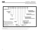
Design Guide - HZH/HZV Series Typical Wiring Diagram – Single Phase HZ Units with Modulating Water Valve 56
LED � � High Pressure Water Switch Heating Relay Ionization Air Purifier Alarm RelayContacts Blower Motor Blower Motor Capacitor Blower Relay Capacitor Circuit Breaker Compressor Contractor Compressor Discharge Temp Sensor Condensate Overflow Sensor Compressor Relay Common Terminal Block Current Sensor Domestic Hot Water Damper Motor Discharge Temperature Switch End Switch Entering Water Temp Sensor Sensor, low temp protection, water coil Sensor, low temp protection, air coil Fan Speed Switch High Pressu
Mate-N-Lock Low Pressure Switch LED High Pressure Switch Ground Control Board Jumper Wire Nut Thermistor Temperature Switch Splice Cap Solenoid Coil Relay/ Contactor Coil Alarm Relay Contacts Blower Motor Blower Motor Capacitor Blower Relay Capacitor Circuit Breaker Compressor Contractor cc CDT Compressor Discharge Temp Sensor Condensate Overflow Sensor co CR Compressor Relay Common Terminal Block CTB Current Sensor cs DHW Domestic Hot Water DM Damper Motor DTS Discharge Temperature Switch E
Low Pressure Switch LED High Pressure Switch Ground Control Board Jumper c::J LAT LOC LOR LWTS MOD MS MSC MWV PB PDB POT Pl PR RAS RVS SAC TB TRANS TS UMT JW DHW DM DTS ES EWTS LT! LT2 FSS HP HPWS HR !AP cs CR CTB co CDT cc AL BM BMC BR CAP CB C] Q o--:;c Splice Cap o-1\,-o Alarm Relay Contacts Blower Motor Blower Motor Capacitor Blower Relay Capacitor Circuit Breaker Compressor Contractor Compressor Discharge Temp Sensor Condensate Overflow Sensor Compressor Relay Common Terminal Block
Design Guide - HZH/HZV Series HZ Series 60Hz Engineering Specifications – Page 1 NOTICE! HZD/H/V SIZE 024-070 60Hz ENGINEERING SPECIFICATIONS General: Furnish and install HZ Water Source Heat Pumps, as indicated on the plans. Equipment shall be completely assembled, piped, and internally wired. Capacities and characteristics as listed in the schedule and the specifications that follow.
Design Guide - HZH/HZV Series HZ Series 60Hz Engineering Specifications – Page 2 filters factory installed, and factory installed unit-mounting brackets. Vertical units to have field installed discharge air duct collar, shipped loose and 1”(25.4mm) filter rails with 1”(25.4mm) filters factory installed.
Design Guide - HZH/HZV Series HZ Series 60Hz Engineering Specifications – Page 3 Option: The unit will be supplied with internally mounted secondary pump for primary/secondary applications, including one-pipe systems. Option: The unit shall be supplied with extended range insulation option, which adds closed cell insulation to internal water lines, and provides insulation on suction side refrigeration tubing including refrigerant to water heat exchanger. Option: Unit shall include ClimaDry® reheat option.
Design Guide - HZH/HZV Series HZ Series 60Hz Engineering Specifications – Page 4 Refrigerant to air heat exchangers shall utilize enhanced corrugated lanced aluminum fins and rifled copper tube or all aluminum microchannel construction rated to withstand 625 PSIG (4309 kPa) refrigerant working pressure.
Design Guide - HZH/HZV Series • • • • • • • • • • • • • • • • • • • • • • • • • • • • • • HZ Series 60Hz Engineering Specifications – Page 5 Random start on power up mode. Low voltage protection. High voltage protection. Unit shutdown on high or low refrigerant pressures (loss of charge). Unit shutdown on low water temperature. Condensate overflow electronic protection. Option to reset unit at thermostat or disconnect. Automatic intelligent reset.
Design Guide - HZH/HZV Series HZ Series 60Hz Engineering Specifications – Page 6 Remote Service Sentinel: Solid state control system shall communicate with thermostat to display (at the thermostat) the unit status, fault status, and specific fault condition, as well as retrieve previously stored fault that caused unit shutdown. The Remote Service Sentinel allows building maintenance personnel or service personnel to diagnose unit from the wall thermostat.
Design Guide - HZH/HZV Series HZ Series 60Hz Engineering Specifications – Page 7 l. m. n. o. p. q. r. fan “ON/AUTO” position of space thermostat as specified above unoccupied/occupied command cooling command heating command fan “ON/AUTO” command fault reset command itemized fault code revealing reason for specific shutdown fault (any one of 7) FIELD INSTALLED OPTIONS Hose Kits: All units shall be connected with hoses.
Design Guide - HZH/HZV Series HZ Series 60Hz Engineering Specifications – Page 8 potable water temperature (on units equipped with a Hot Water Generator). The thermostat shall allow for immediate manual control of all DXM2 outputs at the thermostat for rapid troubleshooting. b. Multistage Digital Automatic Changeover Thermostat shall be multi-stage (2H/2C), manual or automatic changeover with HEAT-OFF-COOL-AUTO-EM HEAT system settings and fan ON-AUTO settings.
Design Guide - HZH/HZV Series DDC Sensors: HZ Series 60Hz Engineering Specifications – Page 9 Wall mounted DDC sensor to monitor room temperature and interfaces with optional interface system described above. Several types as described below: a. Sensor only with no display (LON and MPC). b. Sensor with override (LON only). c. Sensor with setpoint adjustment and override (MPC only). d. Sensor with setpoint adjustment and override, LCD display, status/fault indication (LON and MPC).
Design Guide - HZH/HZV Series Notes 69
Design Guide - HZH/HZV Series Notes 70
Design Guide - HZH/HZV Series Revision History Date: Item: Action: 07/25/19 Pages 66, 68, 69 Updated 7602-457 01/30/19 Page 36, 54 Updated variable pump data Decoder Updated water circuit options 07/14/17 ClimaDry II Added 06/7/17 Dimension H Page 43 Updated 05/03/17 Vertical Upflow Models Dimensional Drawing Updated 05/03/17 Vertical Upflow Models Water Connections Table Updated Update Design Document Updated 03/12/16 Page 57 and 58 Update run test and vflow text 11/7/18 11/1
'XH WR RQJRLQJ SURGXFW LPSURYHPHQWV VSHFLILFDWLRQV DQG GLPHQVLRQV DUH VXEMHFW WR FKDQJH DQG FRUUHFWLRQ ZLWKRXW QRWLFH RU LQFXUULQJ REOLJDWLRQV 'HWHUPLQLQJ WKH DSSOLFDWLRQ DQG VXLWDELOLW\ IRU XVH RI DQ\ SURGXFW LV WKH UHVSRQVLELOLW\ RI WKH LQVWDOOHU $GGLWLRQDOO\ WKH LQVWDOOHU LV UHVSRQVLEOH IRU YHULI\LQJ GLPHQVLRQDO GDWD RQ WKH DFWXDO SURGXFW SULRU WR EHJLQQLQJ DQ\ LQVWDOODWLRQ SUHSDUDWLRQV ,QFHQWLYH DQG UHEDWH SURJUDPV KDYH SUHFLVH UHTXLUHPHQWV DV WR SURGXFW SHUIRUPDQFH DQG FHUWLILFDWLRQ $OO SUR