
Install Instructions


IOM - HZH/HZV Series
35
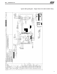
DXM2 Controls
1.6 – DDC output at EH2: DIP 1.6 provides selection
for DDC operation. If set to “DDC Output at EH2,”
the EH2 terminal will continuously output the last fault
code of the controller. If set to “EH2 normal,” EH2 will
operate as standard electric heat output.
On = EH2 Normal. Off = DDC Output at EH2.
1.7– Boilerless operation: DIP 1.7 provides selection
of boilerless operation. In boilerless mode, the
compressor is only used for heating when LT1 is above
the temperature specified by the setting of DIP 1.8.
Below DIP 1.8 setting, the compressor is not used and
the control goes into emergency heat mode, staging
on EH1 and EH2 to provide heating.
On = normal. Off = Boilerless operation.
1.8 – Boilerless changeover temperature: DIP
1.8 provides selection of boilerless changeover
temperature setpoint. Note that the LT1 thermistor is
sensing refrigerant temperature between the coaxial
heat exchanger and the expansion device (TXV).
Therefore, the 50°F [10°C] setting is not 50°F [10°C]
water, but approximately 60°F [16°C] EWT.
On = 50°F [10°C]. Off = 40°F [16°C].
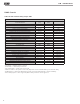
DIP Package #2 (S2) – A combination of dip switches
2.1, 2.2, 2.3, and 2.4, 2.5, 2.6 deliver configuration of
ACC1 and ACC2 relay options respectively. See Table
7a for description and functionality.
2.7 – Auto dehumidification fan mode or high
fan mode: DIP 2.7 provides selection of auto
dehumidification fan mode or high fan mode. In auto
dehumidification mode, the fan speed relay will remain
off during cooling stage 2 IF the H input is active. In
high fan mode, the fan enable and fan speed relays will
turn on when the H input is active.
On = Auto dehumidification mode (default). Off = High
fan mode.
2.8 – Special factory selection: DIP 2.8 provides special
factory selection. Normal position is “On”. Do not
change selection unless instructed to do so by the
factory.
Table 7a: Accessory DIP Switch Settings
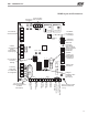
DIP Package #3 (S3)
– DIP Package #3 has 4 switches and provides the
following setup and operating selections:
3.1 – Communications configuration: DIP 3.1 provides
selection of the DXM2 operation in a communicating
system. The DXM2 may operate as the Master of certain
network configurations. In most configurations the
DXM2 will operate as a master device.
On = Communicating Master device (default). Off =
communicating Slave device.
3.2 – HWG Test Mode: DIP 3.2 provides forced operation
of the HWG pump output, activating the HWG pump
output for up to five minutes.
On = HWG test mode. Off = Normal HWG mode
(default).
3.3 – HWG Temperature: DIP 3.3 provides the selection
of the HWG operating setpoint.
On = 150°F [66°C]. Off = 125°F [52°C] (default).
3.4 – HWG Status: DIP 3.4 provides HWG operation
control.
On = HWG mode enabled. Off = HWG mode disabled
(default).
CAUTION!
CAUTION! Do not restart units without inspection and
remedy of faulting condition. Equipment damage may occur.
DIP 2.1 DIP 2.2 DIP 2.3 ACC1 Relay Option
On On On Cycle with fan
Off On On Digital NSB
On Off On Water Valve - slow opening
On On Off OAD
Off Off Off Reheat Option - Humidistat
Off On Off Reheat Option - Dehumidistat
DIP 2.4 DIP 2.5 DIP 2.6 ACC2 Relay Option
On On On Cycle with compressor
Off On On Digital NSB
On Off On Water Valve - slow opening
On On Off OAD
AllÊotherÊDIPÊcombinationsÊa
reÊinvalid