
Install Instructions


IOM - HZH/HZV Series
27
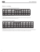
Figure 17: LT1 Limit Setting
Electrical - Low Voltage Wiring
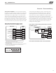
Figure 18: Accessory Wiring
P2 Terminal Strip
Typical
Water
Valve
P1
Alarm
Relay
Comp
Relay
O
Y1
Y2
W
G
C
R
AL1
24Vdc
EH1
EH2
P6
R
C
Off On
JW3
A
OVR
ESD
C
R
NSB
AL2
JW1
Acc1
Relay
Acc2
Relay
H
COM
NC1
NO1
COM
NC2
NO2
P3
CO
RV
RV
LT1
LT1
LT2
LT2
LP
LP
HP
HP
P7
Status
Fault
R
R
CC
CCG
CO
S1
S2
1
12
1
4
Factory Use
(240Vac)
Com
N.O.
Fan Enable
5 1/2"
7"
6 1/2"
5"
Use 4 mounting screws
#6 sheet metal screw 1” long
1.5
3/8” standoff
Factory low
voltage Molex
connection for
unit harness
Factory low
voltage Molex
connection for
electric heat
harness
Micro
U1
Off On
P2
COH
COM
AO2
P11
Gnd
T1
P10
T2 T2 T3 T3 T4 T4
T5
P9
T5
T6 T6
A0-1 A0-2
Off On
S3
RV
Relay
CCH
Relay
Test
P5
B-
Gnd
P4
A+ 24V
(240Vac)
Fan Speed
N.O.
N.C.
12V
OUT
Gnd
P8
IN
NC
P12
Note: There is only
one T1 connection
1 2 3 4
1 2 3 4 5 6 7 8
1 2 3 4 5 6 7 8
AO1
Gnd
1
DXM2 PCB
JW3-LT1 jumper should be clipped for low temperature
(antifreeze) operation
Accessory Connections - A terminal paralleling the
compressor contactor coil has been provided on the DXM2
control. Terminal “A” is designed to control accessory
devices. Note: This terminal should be used only with 24
Volt signals and not line voltage. Terminal “A” is energized
with the compressor contactor.
The DXM2 controller includes two accessory relays ACC1
and ACC2. Each relay includes a normally open (NO) and
a normally closed (NC) contact. Accessory relays may be
configured to operate as shown in the tables below.
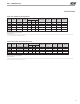
Accessory Relay 2 Configuration
Accessory Relay 1 Configuration
DIP 2.1 DIP 2.2 DIP 2.3 ACC1 Relay Option
ON ON ON Cycle with fan
OFF ON ON N/A for Residential Applications
ON OFF ON Water valve – Slow opening
ON ON OFF Outside air damper
OFF ON OFF ClimaDry option – Dehumidistat
OFF OFF OFF ClimaDry option – Humidistat
OFF OFF ON N/A for Residential Applications
ON OFF OFF N/A for Residential Applications
All other DIP combinations are invalid
DIP 2.4 DIP 2.5 DIP 2.6 ACC2 Relay Option
ON ON ON
Cycle with compressor
OFF ON ON
N/A for Residential Applications
ON OFF ON
Water valve – Slow opening
OFF OFF ON
Humidifier
ON ON OFF
Outside air damper
All other DIP combinations are invalid
Unit Without vFlow
™
- An external solenoid valve(s)
should be used on ground water installations to shut off
flow to the unit when the compressor is not operating.
A slow closing valve may be required to help reduce
water hammer. Figure 18 shows typical wiring for a 24VAC
external solenoid valve. Figures 19 and 20 illustrate
typical slow closing water control valve wiring for Taco
500 series (Comfort-Aire/Century P/N AVM) and Taco
SBV series valves. Slow closing valves take approximately
60 seconds to open (very little water will flow before 45
seconds). Once fully open, an end switch allows the
compressor to be energized. Only relay or triac based
electronic thermostats should be used with slow closing
valves. When wired as shown, the slow closing valve will
operate properly with the following notations:
1. The valve will remain open during a unit lockout.
2. The valve will draw approximately 25-35 VA through
the “Y” signal of the thermostat.
Note: This valve can overheat the anticipator of an
electromechanical thermostat. Therefore, only relay or
triac based thermostats should be used.
Two-stage Units
Two-stage units without vFlow
™
should be designed with
two parallel valves for ground water applications to limit
water use during first stage operation. For example, at 1.5
gpm/ton [2.0 l/m per kW], a HZ048 unit requires 6 gpm [23
l/m] for full load (2nd stage) operation, but only 4 gpm [15
l/m] during 1st stage operation. Since the unit will operate
on first stage 80-90% of the time, significant water savings
can be realized by using two parallel solenoid valves with two
flow regulators. In the example above, stage one solenoid
would be installed with a 4 gpm [15 l/m] flow regulator on
the outlet, while stage two would utilize a 2 gpm [8 l/m] flow
regulator. When stage one is operating, the second solenoid
valve will be closed. When stage two is operating, both
valves will be open, allowing full load flow rate.
Figure 21 illustrates piping for two-stage solenoid valves.
Review figures 18-20 for wiring of stage one valve. Stage
two valve should be wired between terminal “Y2” and
terminal “C.” NOTE: When EWT is below 50°F [10°C], 2
gpm per ton (2.6 l/m per kW) is required.