
Install Instructions


IOM - HZH/HZV Series
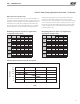
Flexible canvas duct
connector to reduce
noise and vibration
Use turning vanes in
supply transition
Internally insulate return
transition duct to reduce
noise
Rev.: 2/13
Internally insulate supply
duct for the first 4’ (1.2m)
each way to reduce noise
Rounded return
transition
Remove supply duct
flanges from inside blower
compartment and install
on supply air opening of
unit. Do not use a supply
air plenum/duct smaller
than the size of the supply
duct flanges.
Flexible canvas duct
connector to reduce
noise and vibration
Use turning vanes in
supply transition
Internally insulate supply
duct for first 1.2 m each way
to reduce noise
Internally insulate return
transition duct to reduce noise
Rounded return
transition
Remove supply duct
flanges from inside blower
compartment and install
on supply air opening of
unit. Do not use a supply
air plenum/duct smaller
than the size of the supply
duct flanges.
T
H
E
C
O
N
D
E
N
S
A
T
E
F
L
O
W
.
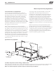
Vertical Installation
Figure 7: Vertical Unit Mounting
Figure 8: Typical Vertical Unit Installation Using
Ducted Return Air
bloque o del ladrillo o sacado
Cojín del aire o sacado
Bloque o ladrillo concreto
Vibration Isolation Pad
Vertical Unit Location - Units are not designed for
outdoor installation. Locate the unit in an INDOOR
area that allows enough space for service personnel to
perform typical maintenance or repairs without removing
unit from the mechanical room/closet. Vertical units
are typically installed in a mechanical room or closet.
Never install units in areas subject to freezing or where
humidity levels could cause cabinet condensation (such
as unconditioned spaces subject to 100% outside air).
Consideration should be given to access for easy removal
of the filter and access panels. Provide sufficient room to
make water, electrical, and duct connection(s).
If the unit is located in a confined space, such as a closet,
provisions must be made for return air to freely enter
the space by means of a louvered door, etc. Any access
panel screws that would be difficult to remove after
the unit is installed should be removed prior to setting
the unit. Refer to Figures 7 and 8 for typical installation
illustrations. Refer to unit submittal data or engineering
design guide for dimensional data.
1. Install the unit on a piece of rubber, neoprene or
other mounting pad material for sound isolation. The
pad should be at least 3/8” [10mm] to 1/2” [13mm] in
thickness. Extend the pad beyond all four edges of
the unit.
2. Provide adequate clearance for filter replacement
and drain pan cleaning. Do not block filter access
with piping, conduit or other materials. Refer to
unit submittal data or engineering design guide for
dimensional data.
3. Provide access for fan and fan motor maintenance
and for servicing the compressor and coils without
removing the unit.
4. Provide an unobstructed path to the unit within the
closet or mechanical room. Space should be sufficient
to allow removal of the unit, if necessary.
5. Provide access to water valves and fittings and
screwdriver access to the unit side panels, discharge
collar and all electrical connections.
Vertical Unit Location
ground loop applications in most climates).
Pipe joint compound is not necessary when Teflon
®
thread tape is pre-applied to hose assemblies or when flared-end
connections are used. If pipe joint compound is preferred, use compound only in small amounts on the external pipe
threads of the fitting adapters. Prevent sealant from reaching the flared surfaces of the joint.
Note: When antifreeze is used in the loop, ensure that it is compatible with the Teflon
®
tape or pipe joint compound that
is applied.
Maximum allowable torque for brass fittings is 30 ft-lbs [41 N-m]. If a torque wrench is not available, tighten finger-tight
plus one quarter turn. Tighten steel fittings as necessary.
Optional pressure-rated hose assemblies designed specifically for use with Comfort-Aire/Century units are available.
Similar hoses can be obtained from alternate suppliers. Supply and return hoses are fitted with swivel-joint fittings at one
end to prevent kinking during installation.
Refer to Figure 12 for an illustration of a typical supply/return hose kit. Adapters secure hose assemblies to the unit and
risers. Install hose assemblies properly and check regularly to avoid system failure and reduced service life.
11