Installation, Operation & Maintenance HZH/V Series www.marsdelivers.
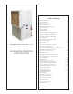
Table of Contents Models HZD/H/V 024 - 070 INSTALLATION, OPERATION, & MAINTENANCE Model Nomenclature General Information Unit Physical Data Horizontal Installation Field Conversion of Air Discharge Horizontal Installation Vertical Installation Piping Installation vFlow™ Heat Pump Applications Overview Water-Loop Heat Pump Applications Ground-Loop Heat Pump Applications Ground-Loop and Ground Water Heat Pump Applications Ground-Water Heat Pump Applications Water Quality Standards Electrical - Line Voltage
IOM - HZH/HZV Series Submittal Data - HZ Series TE Series Nomenclature Model Nomenclature NOTES: 1. Residential class units come standard w/75 VA transformer stainless steel drain pan, ECM motor, and two stage scroll compressors. Units are painted polar ice. 2. Flow controller comes standard with variable speed pump, flushing valves, and expansion tank. Internal flow controller is only available when digit 12 option is selected for copper coax. 3. Motorized valve is two way modulating.
IOM - HZH/HZV Series Storage Pre-Installation General Information Safety Warnings, cautions, and notices appear throughout this manual. Read these items carefully before attempting any installation, service, or troubleshooting of the equipment. DANGER: Indicates an immediate hazardous situation, which if not avoided will result in death or serious injury. DANGER labels on unit access panels must be observed.
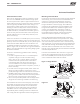
IOM - HZH/HZV Series General Information Examine all pipes, fittings, and valves before installing any of the system components. Remove any dirt or debris found in or on these components. Pre-Installation - Installation, Operation, and Maintenance instructions are provided with each unit. Horizontal equipment is designed for installation above false ceiling or in a ceiling plenum. Other unit configurations are typically installed in a mechanical room.
IOM - HZH/HZV Series Unit Physical Data Model 024 036 Compressor (1 Each) 048 060 070 Two-Stage Scroll Factory Charge (HFC-410A) (oz) [kg] 44 [1.25] 52 [1.47] 69 [1.96] 142 [4.03] 140 [3.97] Fan Motor (hp) [W] 1/2 [373] 1/2 [373] 1 [746] 1 [746] 1 [746] Blower Wheel Size (dia x w) (in) [mm] 9 x 7 [229 x 178] 11 x 10 [279 x 254] 11 x 10 [279 x 254] 11 x 10 [279 x 254] 11 x 10 [279 x 254] 1 1 1 1 1 1/2 1/2 1/2 1/2 1/2 0.76 [2.88] 0.92 [3.48] 1.24 [4.69] 1.56 [5.91] 1.
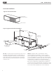
IOM - HZH/HZV Series Horizontal Installation Horizontal Unit Location Units are not designed for outdoor installation. Locate the unit in an INDOOR area that allows enough space for service personnel to perform typical maintenance or repairs without removing unit from the ceiling. Horizontal units are typically installed above a false ceiling or in a ceiling plenum.
IOM - HZH/HZV Series Horizontal Installation Figure 2: Horizontal Unit Pitch 1/4” (6.4mm) pitch toward drain for drainage Drain Connection Figure 3: Typical Horizontal Unit Installation 3/8” [10mm] thread rods (by others) Thermostat Wiring Stainless Steel Braid Hose with Integral “J” Swivel Power Wiring Suppy Air Unit Power Building Loop Insulated supply duct with at least on 90 deg.
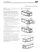
IOM - HZH/HZV Series Field Conversion of Air Discharge Overview - Horizontal units can be field converted between side (straight) and back (end) discharge using the instructions below. Figure 4: Left Return Side to Back Remove Screws Water Connection End Note: It is not possible to field convert return air between left or right return models due to the necessity of refrigeration copper piping changes. Return Air Preparation - It is best to field convert the unit on the ground before hanging.
FLOW. CONDENSATE THE IOM - HZH/HZV Series Horizontal Installation Condensate Piping - Horizontal Units - A condensate drain line must be installed and pitched away for the unit to allow for proper drainage. This connection must meet all local plumbing/building codes. Pitch the unit toward the drain as shown in Figure 2 to improve the condensate drainage. On small units (less than 2.5 tons/8.8 kW), ensure that unit pitch does not cause condensate leaks inside the cabinet.
FLOW. CONDENSATE THE IOM - HZH/HZV Series ground loop applications in most climates). Pipe joint compound is not necessary when Teflon® thread tape is pre-applied to hose assemblies or when flared-end connections are used. If pipe joint compound is preferred, use compound only in small amounts on the external pipe threads of the fitting adapters. Prevent sealant from reaching the flared surfaces of the joint.
IOM - HZH/HZV Series Vertical Installation Notice! Installation Note - Ducted Return: Many horizontal WSHPs are installed in a return air ceiling plenum application (above ceiling). Vertical WSHPs are commonly installed in a mechanical room with free return (e.g. louvered door). Therefore, filter rails are the industry standard and are included on Comfort-Aire/Century commercial heat pumps for the purposes of holding the filter only.
IOM - HZH/HZV Series Piping Installation Installation of Supply and Return Piping Follow these piping guidelines. 1. Install a drain valve at the base of each supply and return riser to facilitate system flushing. 2. Install shut-off / balancing valves and unions at each unit to permit unit removal for servicing. 3. Place strainers at the inlet of each system circulating pump. 4. Select the proper hose length to allow slack between connection points. Hoses may vary in length by +2% to -4% under pressure.
IOM - HZH/HZV Series vFlow™ Heat Pump Applications Overview vFlow™ is a revolutionary new, intelligent, and efficient way to circulate water (or water plus antifreeze) using internal, variable speed water flow control. The factory installed high efficiency variable speed pumps uses almost half the wattage of traditional fixed speed pump.
IOM - HZH/HZV Series vFlow™ Heat Pump Applications Overview - Continued Water Pressure Schrader Ports The pressure ports built in to the unit are provided as a means of measuring pressure drop through the water-torefrigerant heat exchanger. The water pressure ports are schrader ports smaller than refrigerant schrader ports. They are the same size as tire schrader ports. A digital pressure gauge is recommended for taking pressure readings through these ports.
IOM - HZH/HZV Series High Head Variable Pump with Check Valve 50 45 40 Head (feet) 35 30 25 20 15 10 5 0 0 5 10 15 GPM 16 20 25
IOM - HZH/HZV Series Water-Loop Heat Pump Applications Commercial Water Loop Applications Commercial systems typically include a number of units connected to a common piping system. Any unit plumbing maintenance work can introduce air into the piping system; therefore air elimination equipment is a major portion of the mechanical room plumbing. Consideration should be given to insulating the piping surfaces to avoid condensation.
IOM - HZH/HZV Series Ground-Loop Heat Pump Applications � CAUTION! � CAUTION! The following instructions represent industry accepted installation practices for closed loop earth coupled heat pump systems. Instructions are provided to assist the contractor in installing trouble free ground loops. These instructions are recommendations only. State/provincial and local codes MUST be followed and installation MUST conform to ALL applicable codes.
IOM - HZH/HZV Series Ground-Loop and Ground Water Heat Pump Applications Figure 13: Ground-Loop Heat Pump Applications Typical Closed Loop with Central Pumping (unit with internal modulating water valve) To Thermostat Internal Motorized Modulating Valve Water Out High and Low Voltage Knockouts Water In Shut Off Ball Valves for Isolation Vibration Isolation Pad Ground Water Heat Pump Applications Typical Open Loop/Well (unit with internal modulating water valve) To Thermostat Internal Motorized Modu
IOM - HZH/HZV Series Ground-Water Heat Pump Applications Open Loop - Ground Water Systems - Typical open loop piping is shown in accompanying illustration. Shut off valves should be included for ease of servicing. Boiler drains or other valves should be “tee’d” into the lines to allow acid flushing of the heat exchanger. Shut off valves should be positioned to allow flow through the coax via the boiler drains without allowing flow into the piping system.
IOM - HZH/HZV Series Ground-Water Heat Pump Applications Flow Regulation - Units without vFlow™ - Flow regulation can be accomplished by two methods. One method of flow regulation involves simply adjusting the ball valve or water control valve on the discharge line. Measure the pressure drop through the unit heat exchanger, and determine flow rate from Table 10. Since the pressure is constantly varying, two pressure gauges may be needed. Adjust the valve until the desired flow of 1.5 to 2 gpm per ton [2.
IOM - HZH/HZV Series Water Quality Standards Table 3: Water Quality Standards Water Quality Parameter HX Material Closed Recirculating Open Loop and Recirculating Well Scaling Potential - Primary Measurement Above the given limits, scaling is likely to occur. Scaling indexes should be calculated using the limits below pH/Calcium Hardness Method All - pH < 7.
IOM - HZH/HZV Series Electrical - Line Voltage Electrical - Line Voltage - All field installed wiring, including electrical ground, must comply with the National Electrical Code as well as all applicable local codes. Refer to the unit electrical data for fuse sizes. Consult wiring diagram for field connections that must be made by the installing (or electrical) contractor.
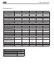
IOM - HZH/HZV Series Electrical - Line Voltage Standard Units, Units with Modulating Motorized Valve Compressor Model Voltage Code Voltage Min/Max Voltage 024 1 208/230/60/1 197/252 11.7 036 1 208/230/60/1 197/252 15.3 048 1 208/230/60/1 197/252 21.2 RLA Qty Fan Motor FLA Total Unit FLA Min Circ Amp Max Fuse/ HACR 58.3 1 3.9 15.6 18.5 30 83.0 1 3.9 19.2 23.0 35 104.0 1 6.9 28.1 33.4 50 LRA 060 1 208/230/60/1 197/252 27.1 152.9 1 6.9 34.0 40.
IOM - HZH/HZV Series Electrical Data Units with Variable Pump High Head Model Voltage Code Voltage Min/Max Voltage 024 1 208/230/60/1 036 1 208/230/60/1 048 1 060 1 070 1 Compressor Pump FLA Fan Motor FLA Total Unit FLA Min Circ Amp Max Fuse/ HACR 1 1.44 3.9 17.0 20.0 30 1 1.44 3.9 20.6 24.5 40 104.0 1 1.44 6.9 29.5 34.8 50 152.9 1 1.44 6.9 35.4 42.2 60 179.2 1 1.44 6.9 38.0 45.5 70 RLA LRA Qty 197/252 11.7 58.3 197/252 15.3 83.
IOM - HZH/HZV Series Electrical - Power & Low Voltage Wiring � WARNING! � WARNING! Disconnect electrical power source to prevent injury or death from electrical shock. � CAUTION! � CAUTION! Use only copper conductors for field installed electrical wiring. Unit terminals are not designed to accept other types of conductors. Power Connection - Line voltage connection is made by connecting the incoming line voltage wires to the “L” side of the contractor as shown in the unit wiring diagram.
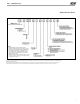
Fan Speed IOM - HZH/HZV Series P8 Test Alarm Relay JW1 1 Fault Status On Off On 1 2 3 4 5 6 7 8 Acc1 Relay S1 On 1 2 3 4 5 6 7 8 S3 Off S2 A0-1 A0-2 JW3 RV Relay CCH Relay AO1 Gnd AO2 Gnd HP HP LP LP LT1 LT1 LT2 LT2 RV RV CO 12 CO Figure 18: Accessory Wiring 6 1/2" P7 1 24Vdc EH1 4 EH2 Comp Relay Acc2 Relay P11 Electrical - Low Voltage Wiring 1 Figure 17: LT1 Limit Setting Off 12V IN OUT Gnd NC P12 Micro U1 1 2 3 4 M Fan Enable Factory Use OH Com P10 P6 CCG P9 T1 T
IOM - HZH/HZV Series Electrical - Low Voltage Wiring for non-vFlow™ Units Using External Motorized Water Valve Water Valve Wiring 2 3 AVM Taco Valve Y1 Heater Switch C 1 DXM2 Figure 20: Taco SBV Valve Wiring Y1 C Figure 19: AVM Valve Wiring Aquastat C Y Unidad Empacada Figure 21: Two-Stage Piping Solenoid Valve 1 2 Calentador Interruptor 3 Flow Regulator AVM Taco Válvula Stage 2 To Discharge OUT Stage 1 From Water Source Y C IN Termostato 28 NOTE: Shut-off valves, strainers a
IOM - HZH/HZV Series Figure 24a: Communicating Thermostat Connection to DXM2 Control iGate® Thermostat ATC32U03 Gnd Thermostat Installation - The should be 24Vac Common Comm + thermostat C A+ located onHot an interior wall in -a larger BComm B- room, away from 24Vac R supply duct drafts. DO NOT locate the thermostatA+in areas subject to sunlight, drafts or on external walls.
IOM - HZH/HZV Series Blower Performance Data Airflow in CFM with wet coil and clean air filter Model Max ESP (in wg) Fan Motor (hp) Range 024 1.0 1/2 036 048 060 070 0.9 1.0 0.7 0.
IOM - HZH/HZV Series ECM Blower Control The ECM fan is controlled directly by the DXM2 control board that converts thermostat inputs and CFM settings to signals used by the ECM motor controller. To take full advantage of the ECM motor features, a communicating multi-stage thermostat should be used (7602-457). The DXM2 control maintains a selectable operating airflow [CFM] for each heat pump operating mode. For each operating mode there are maximum and minimum airflow limits.
Low LED L Pressure Switch High Pressure Switch Ground Control B oard Jumper OVERLOAD WireNut C] B MC BM B lower B lower Alarm Relay Contacts Motor Motor Capacitor B lower Relay BR CAP Capacitor CB Circuit Breaker Compressor Contractor cc CDT Compressor Discharge Temp Sensor Condensate Overflow Sensor co CR Compressor Relay Common Terminal Block CTB Current Sensor cs DHW Domestic Hot Water DM Damper Motor DTS Discharge Temperature Switch End Switch ES EWTS Entering Water Temp Sensor LT! Sen
� � High Pressure Water Switch Heating Relay Ionization Air Purifier Alarm RelayContacts Blower Motor Blower Motor Capacitor Blower Relay Capacitor Circuit Breaker Compressor Contractor Compressor Discharge Temp Sensor Condensate Overflow Sensor Compressor Relay Common Terminal Block Current Sensor Domestic Hot Water Damper Motor Discharge Temperature Switch End Switch Entering Water Temp Sensor Sensor, low temp protection, water coil Sensor, low temp protection, air coil Fan Speed Switch High Pressure Sw
IOM - HZH/HZV Series DXM2 Controls DXM2 Control - For detailed control information, see DXM2 Application, Operation and Maintenance (AOM) manual (part # 97B0003N15). DIP Switches – Note: In the following field configuration options, DIP switches should only be changed when power is removed from the DXM2 control. Field Selectable Inputs - Test mode: Test mode allows the service technician to check the operation of the control in a timely manner.
IOM - HZH/HZV Series DXM2 Controls 1.6 – DDC output at EH2: DIP 1.6 provides selection for DDC operation. If set to “DDC Output at EH2,” the EH2 terminal will continuously output the last fault code of the controller. If set to “EH2 normal,” EH2 will operate as standard electric heat output. On = EH2 Normal. Off = DDC Output at EH2. 1.7– Boilerless operation: DIP 1.7 provides selection of boilerless operation.
IOM - HZH/HZV Series DXM2 Controls Table 7b: LED and Alarm Relay Output Table DMX2 CONTROLLER FAULT CODES DMX2 Fault and Status LED Operation with Test Mode Not Active Fault LED (Red) Status LED (Green) Alarm Relay DXM2 Is Non-Functional Off Off Open Normal Operation - No Active Communications On On Open Normal Operation - With Active Communications Very Slow Flash ON Open Control Is Currently In Fault Retry Mode Slow Flash - Open Control Is Currently Locked Out Fast Flash - Closed Co
IOM - HZH/HZV Series DXM2 Controls 5" DXM2 Control Start-up Operation – The control will not operate until all inputs and safety controls are checked for normal conditions. The compressor will have a 5 minute anti-short cycle delay at power-up. The first time P1 after power-up that there is a call for compressor, the Y1 compressor will follow a 5 to 80 second random start delay. Y2 After the random start delay and anti-short cycle delay, W the compressor relay will be energized.
IOM - HZH/HZV Series DXM2 Controls Table 8: Nominal Resistance at Various Temperatures 38 Temp (ºC) Temp (ºF) -17.8 -17.5 -16.9 -12 -11 -10 -9 -8 -7 -6 -5 -4 -3 -2 -1 0 1 2 3 4 5 6 7 8 9 10 11 12 13 14 15 16 17 18 19 20 21 22 23 24 25 26 27 28 29 30 31 32 33 34 35 36 37 38 39 40 41 42 43 44 45 46 47 48 49 50 51 52 53 54 0.0 0.5 1.5 10.4 12.2 14.0 15.8 17.6 19.4 21.2 23.0 24.8 26.6 28.4 30.2 32.0 33.8 35.6 37.4 39.2 41.0 42.8 44.6 46.4 48.2 50.0 51.8 53.6 55.4 57.2 59.0 60.8 62.6 64.4 66.2 68.0 69.
IOM - HZH/HZV Series DXM2 Layout and Connections Service tool Communicating5" connection stat connection C P1 Gnd B- A+ 24V P5 R Y1 P4 Conventional stat connection N.C. N.O. Com Y2 (240Vac) (240Vac) N.O.
IOM - HZH/HZV Series ClimaDry II Modulating Reheat Option ClimaDry II Sequence Of Operation A heat pump equipped with ClimaDry II can operate in three modes, cooling, cooling with reheat, and heating. The cooling/heating modes are like any other Comfort-Aire/ Century WSHP. The reversing valve (“O” signal) is energized in cooling, along with the compressor contactor(s) and blower relay. In the heating mode the reversing valve is de-energized.
IOM - HZH/HZV Series ClimaDry II Modulating Reheat Option The Loop Pump circulates condenser water through the hydronic reheat coil during the reheat mode of operation. In this application, the loop pump is only energized during the reheat mode of operation. The Hydronic Coil is utilized during the reheat mode of operation to reheat the air to the setpoint of the proportional controller.
IOM - HZH/HZV Series ClimaDry II Modulating Reheat Option Table 8a: Humidistat/Dehumidistat Logic & DXM (2.1, 2.2., 2.3) DIP Settings Sensor 2.1 2.2 2.
IOM - HZH/HZV Series Unit Starting and Operating Conditions Operating Limits Environment – Units are designed for indoor installation only. Never install units in areas subject to freezing or where humidity levels could cause cabinet condensation (such as unconditioned spaces subject to 100% outside air). Power Supply – A voltage variation of +/– 10% of nameplate utilization voltage is acceptable. Determination of operating limits is dependent primarily upon three factors: 1) return air temperature.
IOM - HZH/HZV Series Piping System Cleaning and Flushing Piping System Cleaning and Flushing - Cleaning and flushing the WLHP piping system is the single most important step to ensure proper start-up and continued efficient operation of the system. Follow the instructions below to properly clean and flush the system: 1. Ensure that electrical power to the unit is disconnected. 2. Install the system with the supply hose connected directly to the return riser valve. Use a single length of flexible hose. 3.
IOM - HZH/HZV Series Flushing/Purging Units with ClimaDry II When flushing/purging units equipped with ClimaDry II the unit should be fully flushed/purged before attempting to flush/purge the ClimaDry II coil. Once the unit is flushed, energize the modulating threeway dehumidification valve to allow flow through the ClimaDry II hydronic circuit. De-energize the valve by removing the red wire from the ACC1 ‘NC’ terminal on the DXM2 board.
IOM - HZH/HZV Series Unit and System Checkout � WARNING! � WARNING! Polyolester Oil, commonly known as POE oil, is a synthetic oil used in many refrigeration systems including those with HFC-410A refrigerant. POE oil, if it ever comes in contact with PVC or CPVC piping, may cause failure of the PVC/CPVC. PVC/CPVC piping should never be used as supply or return water piping with water source heat pump products containing HFC-410A as system failures and property damage may result.
IOM - HZH/HZV Series Unit Start-Up Procedure Unit Start-up Procedure 1. Turn the thermostat fan position to “ON”. Blower should start. 2. Balance air flow at registers. 3. Adjust all valves to their full open positions. Turn on the line power to all heat pumps. 4. Room temperature should be within the minimummaximum ranges of table 9b. During start-up checks, loop water temperature entering the heat pump should be between 60°F [16°C] and 95°F [35°C]. 5.
IOM - HZH/HZV Series Unit Operating Conditions Table 10: HZ Coax Water Pressure Drop Model 024 036 048 060 070 48 GPM 2.3 3.0 3.4 4.5 6.0 3.0 4.5 6.0 6.8 9.0 4.5 6.0 6.8 9.0 12.0 6.0 7.5 9.0 11.3 12.0 15.0 7.0 8.5 10.5 12.8 14.0 17.0 30ºF 0.47 0.68 0.79 1.14 1.75 0.91 1.52 2.21 2.62 3.92 0.24 0.89 1.19 2.13 3.82 0.9 1.7 2.5 3.7 4.1 6.1 1.4 2.2 3.3 4.6 5.4 7.6 Pressure Drop (psi) 50ºF 0.41 0.60 0.70 1.01 1.56 0.79 1.30 1.89 2.25 3.41 0.11 0.72 1.00 1.87 3.48 0.2 0.9 1.5 2.6 3.0 4.7 0.7 1.3 2.2 3.
IOM - HZH/HZV Series Unit Operating Conditions Table 11: HZ Series Typical Unit Operating Pressures and Temperatures (60Hz – I-P Units) HZ024 Full Load Cooling - without HWG active Entering Water Suction Water Flow Pressure Temp GPM/ton PSIG °F Discharge Pressure PSIG Superheat Subcooling Water Temp Rise °F 30* 1.5 2.25 3 50 1.5 2.25 3 128-138 128-138 128-138 186-206 172-192 158-178 18-23 18-23 18-23 8-13 6-11 6-11 16.3-18.3 12.1-14.1 7.8-9.8 70 1.5 2.
IOM - HZH/HZV Series Unit Operating Conditions HZ060 Entering Water Water Flow Temp GPM/ton °F Suction Pressure PSIG Full Load Cooling - without HWG active Water Temp Superheat Subcooling Rise °F Discharge Pressure PSIG 30* 1.5 2.25 3 50 1.5 2.25 3 128-138 126-136 125-135 238-258 222-242 205-225 16-21 21-26 26-31 14-19 13-18 12-17 20.5-22.5 14.9-16.9 9.2-11.2 70 1.5 2.25 3 135-145 134-144 133-143 315-335 296-316 276-296 10-15 12-17 15-20 14-19 13-18 11-16 90 1.5 2.
IOM - HZH/HZV Series Preventive Maintenance Water Coil Maintenance - (Direct ground water applications only) If the system is installed in an area with a known high mineral content (125 P.P.M. or greater) in the water, it is best to establish a periodic maintenance schedule with the owner so the coil can be checked regularly. Consult the well water applications section of this manual for a more detailed water coil material selection.
IOM - HZH/HZV Series Troubleshooting General If operational difficulties are encountered, perform the preliminary checks below before referring to the troubleshooting charts. • Verify that the unit is receiving electrical supply power. • Make sure the fuses in the fused disconnect switches are intact. After completing the preliminary checks described above, inspect for other obvious problems such as leaking connections, broken or disconnected wires, etc.
IOM - HZH/HZV Series Troubleshooting (Continued) Advanced Diagnostics If a communicating thermostat or diagnostic tool (7602444) is connected to the DXM2, additional diagnostic information and troubleshooting capabilities are available. The current status of all DXM2 inputs can be verified, including the current temperature readings of all temperature inputs. With a communicating thermostat the current status of the inputs can be accessed from the Service Information menu.
IOM - HZH/HZV Series DXM2 Process Flow Chart � WARNING! � WARNING! HAZARDOUS VOLTAGE! DISCONNECT ALL ELECTRIC POWER INCLUDING REMOTE DISCONNECTS BEFORE SERVICING. Failure to disconnect power before servicing can cause severe personal injury or death.
IOM - HZH/HZV Series Functional Troubleshooting Fault Main power problems HP Fault Code 2 Htg Clg Possible Cause Air temperature out of range in heating Overcharged with refrigerant Bad HP Switch Insufficient charge Check line voltage circuit breaker and disconnect. Check for line voltage between L1 and L2 on the contactor. Check for 24VAC between R and C on CXM/DXM' Check primary/secondary voltage on transformer. Check pump operation or valve operation/setting.
IOM - HZH/HZV Series Functional Troubleshooting (cont.
IOM - HZH/HZV Series Performance Troubleshooting Symptom Htg Clg Possible Cause X X Dirty filter Reduced or no air flow in heating X X Reduced or no air flow in cooling Solution Replace or clean Check for dirty air filter and clean or replace Check fan motor operation and airflow restrictions Too high of external static - check static vs blower table Check for dirty air filter and clean or replace Check fan motor operation and airflow restrictions Too high of external static - check static vs blowe
X X X X X X Unit over charged Non-condensables insystem Restricted metering device X Reduced water flow in heating X Water temperature out of range Low Suction Pressure Reduced air flow X Performance Troubleshooting (continued) in cooling X Symptom Low Dischage Air Temperature in Heating High Humidity Insufficient Capacity/ Not Cooling or Heating Only Compressor Runs Properly Unit Doesn't Operate in Cooling X X Insufficient charge Htg Clg Possible Cause X X X X X X X X X X X X Leaky du
IOM - HZH/HZV Series Start-Up Log Sheet Installer: Complete unit and system checkout and follow unit start-up procedures in the IOM. Use this form to record unit information, temperatures and pressures during start-up. Keep this form for future reference.
Location: ________________________ Model Number: ________________________ IOM - HZH/HZV Series Serial Number: ________________________ Date: ________________________ Packaged Unit Refrigeration Schematic Customer: _____________________________________ Antifreeze: ________________________ Model#: ________________________ Serial#: ________________ Loop type: _______________ Functional Troubleshooting Complaint: Circuit ________________________________________________________________________ Refrigerant Diag
LIMITED EXPRESS WARRANTY Congratulations on purchasing your new HVAC equipment. It’s been designed for long life and reliable service, and is backed by one of the strongest warranties in the industry. Your unit automatically qualifies for the warranty coverage listed below, providing you keep your proof of purchase (receipt) for the equipment and meet the warranty conditions.
IOM - HZH/HZV Series Notes 62
IOM - HZH/HZV Series Notes 63
Revision History Date: Item: Action: 01/30/19 Page 15, 16, 25 Update variable heat pump data 11/8/18 Decoder Updated water circuit options 07/25/17 Page 7 Update hanger and mounting instructions 06/19/17 ClimaDry II Option Added 10/7/16 Page 7 Text Update 04/15/16 Text Updated 06/12/15 Decoder - Page 3; Text - Page 25 Updated 09/30/14 Text Edit - Page 14 Updated 07/21/14 First Published 'XH WR RQJRLQJ SURGXFW LPSURYHPHQWV VSHFLILFDWLRQV DQG GLPHQVLRQV DUH VXEMHFW WR FKDQJH DQG