
Install Instructions


Installation Manual - DVC/DVH 09/12/18/24 Series
Page 22
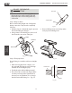
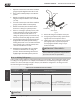
If you will install the unit on the ground or
on a concrete mounting platform, do the
following:
1. Mark the positions for four expansion bolts
based on dimensions in the Unit Mounting
Dimensions chart.
2. Pre-drill holes for expansion bolts.
3. Clean concrete dust away from holes.
4. Place a nut on the end of each expansion bolt.
5. Hammer expansion bolts into the pre-drilled
holes.
6. Remove the nuts from expansion bolts, and
place outdoor unit on bolts.
7. Put washer on each expansion bolt, then
replace the nuts.
8. Using a wrench, tighten each nut until snug.
WARNING
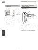
Step 3: Anchor outdoor unit
The outdoor unit can be anchored
to the ground or to a wall-mounted
bracket.
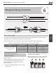
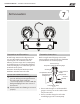
UNIT MOUNTING DIMENSIONS
The following is a list of different
outdoor unit sizes and the distance
between their mounting feet.
Prepare the installation base of the
unit according to the dimensions
below.
A
W
B
D
Air inlet
Air outlet
Air inlet
A
W
B
D
Air inlet
Air outlet
Air inlet
Fig. 4.5
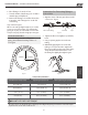
Outdoor Unit
Installation
WHEN DRILLING INTO CONCRETE, EYE
PROTECTION IS RECOMMENDED AT ALL
TIMES.
Outdoor Unit Dimensions (mm/in)
W x H x D
Mounting Dimensions
Distance A (mm/in) Distance B (mm/in)
DVC/DVH 09
460 (18.10”) 292 (11.49”)
700x550x270 (27.5”x21.6”x10.62”) 450 (17.7”) 260 (10.24”)
DVC/DVH 12
549 (21.6”) 276 (10.85”)
845x700x320 (33.25”x27.5”x12.6”) 560 (22”) 335 (13.2”)
DVC/DVH 18
549 (21.6”) 325 (12.8”)
700x550x275 (27.5”x21.6”x10.82”) 450 (17.7”) 260 (10.24”)
DVC/DVH 24
487 (19.2”) 298 (11.73”)
800x554x333 (31.5”x21.8”x13.1”) 514 (20.24”) 340 (13.39”)
21