Owner’s Manual & Installation Manual DVH Series Inverter Single Zone Ductless Mini-Split DVH09SG-0 DVH09SG-1 DVH12SG-0 DVH12SG-1 DVH18SG-1 DVH24SG-1 www.marsdelivers.
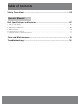
Table of Contents Safety Precautions ...............................................................................03 Owner’s Manual Unit Specifications and Features...........................................................07 1. Indoor unit display.........................................................................................................................07 2. Operating temperature.................................................................................................................
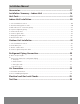
Installation Manual Accessories..........................................................................................17 Installation Summary - Indoor Unit .................................................18 Unit Parts.............................................................................................19 Indoor Unit Installation......................................................................20 1. Select installation location...................................................................
1900 Wellworth Jackson, MI 49203 Attention ALL INVERTER MINI-SPLITS REQUIRE 14-4 STRANDED WIRE BETWEEN THE INDOOR AND OUTDOOR UNITS (NO EXCEPTIONS) 14 AWG 4/C TRAY CABLE A14/4SRBTHHNBK 14 AWG (19/0147) BC 4/C, THHN CONDUCTORS POWER & CONTROL TRAY CABLE TYPE TC CABLE FOR INSTALLATION IN ACCORDANCE WITH ARTICLE 336 AND OTHER APPLICABLE PARTS OF THE NATIONAL ELECTRICAL CODE.
Safety Precautions Safety Safety Precautions Read Safety Precautions Before Operation and Installation Incorrect installation due to ignoring instructions can cause serious damage or injury. The seriousness of potential damage or injuries is classified as either a WARNING or CAUTION. WARNING This symbol indicates the possibility of personnel injury or loss of life. CAUTION This symbol indicates the possibility of property damage or serious consequences.
Safety Precautions CLEANING AND MAINTENANCE WARNINGS • Turn off the device and disconnect the power before cleaning. Failure to do so can cause electrical shock. • Do not clean the air conditioner with excessive amounts of water. • Do not clean the air conditioner with combustible cleaning agents. Combustible cleaning agents can cause fire or deformation. • • • • • • • • • • • • • • • • CAUTION Turn off the air conditioner and disconnect the power if you are not going to use it for a long time.
Safety Precautions WARNINGS FOR PRODUCT INSTALLATION 1. Installation must be performed by an authorized dealer or specialist. Defective installation can cause water leakage, electrical shock, or fire. 2. Installation must be performed according to the installation instructions. Improper installation can cause water leakage, electrical shock, or fire. (In North America,installation must be performed in accordance with the requirement of NEC and CEC by authorized personnel only.) 3.
Safety Precautions WARNING for Using R32/R290 Refrigerant When flammable refrigerant are employed, appliance shall be stored in a well-ventilated area where the room size corresponds to the room area as specific for operation. For R32 refrigerant models: Appliance shall be installed, operated and stored in a room with a floor area larger than 14 ft. Appliance shall not be installed in an unventilated space, if that space is smaller than 14 ft.
Unit Specifications and Features NOTE: Different models have different front panel and display windows. Not all the indicators described below are available for the air conditioner you purchased. Please check the indoor display window of the unit you purchased. Illustrations in this manual are for explanatory purposes. The actual shape of your indoor unit may vary. The actual shape shall prevail.
Unit Specifications and Features Power Cable (Some Units ) Front Panel Remote Control Louver Remote Control Holder (Some Units) Functional Filter (On Back of Main Filter - Some Units) Display window (E) “ Display window The unit has a built-in light sensor to detect the ambient brightness. When the light is turned off, the display will be off after 7 seconds, saving energy and offering you a comfortable sleep.
Operating temperature When your air conditioner is used outside of the following temperature ranges, certain safety protection features may activate and cause the unit to disable. Room Temperature COOL mode HEAT mode DRY mode 17°C - 32°C (62°F - 90°F) 0°C - 30°C (32°F - 86°F) 10°C - 32°C (50°F - 90°F) -15°C - 30°C (5°F - 86°F) 0°C - 50°C (32°F - 122°F) 0°C - 50°C (32°F - 122°F) -15°C - 50°C (5°F - 122°F) Outdoor Temperature (For models with low temp. cooling systems.
Unit Specifications and Features A guide on using the infrared remote is not included in this literature package. Not all the functions are available for the air conditioner, please check the indoor display and remote control of the unit you purchased. Other Features • Auto-Restart(some units) If the unit loses power, it will automatically restart with the prior settings once power has been restored.
• Setting Angle of Air Flow Setting vertical angle of air flow Ra NOTE ON LOUVER ANGLES When using COOL or DRY mode, do not set louver at too vertical an angle for long periods of time. This can cause water to condense on the louver blade, which will drop on your floor or furnishings. When using COOL or HEAT mode, setting the louver at too vertical an angle can reduce the performance of the unit due to restricted air flow.
Care and Maintenance Cleaning Your Indoor Unit BEFORE CLEANING OR MAINTENANCE 6. Rinse the filter with fresh water, then shake off excess water. 7. Dry it in a cool, dry place, and refrain from exposing it to direct sunlight. Care and Maintenance 8. When dry, re-clip the air freshening filter to ALWAYS TURN OFF YOUR AIR CONDITIONER the larger filter, then slide it back into the SYSTEM AND DISCONNECT ITS POWER SUPPLY indoor unit. BEFORE CLEANING OR MAINTENANCE. 9.
CAUTION • Before changing the filter or cleaning, If you plan not to use your air conditioner for an extended period of time, do the following: Clean all filters Turn on FAN function until unit dries out completely Turn off the unit and disconnect the power Remove batteries from remote control Air Filter Reminders (Optional) Air Filter Cleaning Reminder After 240 hours of use, the display window on the indoor unit will flash “CL.” This is a reminder to clean your filter.
Troubleshooting SAFETY PRECAUTIONS If ANY of the following conditions occurs, turn off your unit immediately! • The power cord is damaged or abnormally warm • You smell a burning odor • The unit emits loud or abnormal sounds • A power fuse blows or the circuit breaker frequently trips • Water or other objects fall into or out of the unit DO NOT ATTEMPT TO FIX THESE YOURSELF! CONTACT AN AUTHORIZED SERVICE PROVIDER IMMEDIATELY! Troubleshooting Common Issues The following problems are not a malfunction and i
Issue Possible Causes The outdoor unit makes noises The unit will make different sounds based on its current operating mode. Dust is emitted from either the indoor or outdoor unit The unit may accumulate dust during extended periods of non-use, which will be emitted when the unit is turned on. This can be mitigated by covering the unit during long periods of inactivity.
Problem The unit is not working The unit starts and stops frequently Troubleshooting Poor heating performance Indicator lamps continue flashing Error code appears and begins with the letters as the following in the window display of indoor unit: • E(x), P(x), F(x) • EH(xx), EL(xx), EC(xx) • PH(xx), PL(xx), PC(xx) Possible Causes Solution Power failure Wait for the power to be restored The power is turned off Turn on the power The fuse is burned out Replace the fuse Remote control batteries are
Accessories The air conditioning system comes with the following accessories. Use all of the installation parts and accessories to install the air conditioner. Improper installation may result in water leakage, electrical shock and fire, or cause the equipment to fail. The items are not included with the air conditioner must be purchased separately.
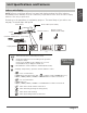
Installation Summary - Indoor Unit 1 2 At least 6" (15cm) At Least 6" (15cm) 3 At Least 6" (15cm) At least 64" (163cm) Select Installation Location 5 44 Drill Wall Hole Installation Summary -Indoor Unit 7 Prepare Drain Hose Attach Mounting Plate Determine Wall Hole Position 6 Connect Piping Connect Wiring (not applicable for some locations in the US ) 8 Wrap Piping and Cable (not applicable for some locations in the US ) 9 STEP 8 Mount Indoor Unit Page 18
Unit Parts NOTE: The installation must be performed in accordance with the requirement of local and national standards. The installation may be slightly different in different areas.
Indoor Unit Installation Installation Instructions – Indoor unit PRIOR TO INSTALLATION Before installing the indoor unit, refer to the label on the product box to make sure that the model number of the indoor unit matches the model number of the outdoor unit. Step 1: Select installation location Before installing the indoor unit, you must choose an appropriate location. The following are standards that will help you choose an appropriate location for the unit.
179mm (7.05in) 136mm (5.35in) 49mm (1.95in) Indoor unit outline Left rear wall hole 65mm (2.5in) 49mm (1.95in) 290mm (11.4in) 101mm (4in) 722mm (28.45in) Right rear wall hole 65mm (2.5in) Model A 401mm (15.78in) 42mm (1.65in) 229mm (9.01in) 228mm (8.98in) 47mm (1.85in) 126mm (4.96in) Left rear wall hole 65mm (2.5in) 58mm (2.28in) Indoor unit outline Right rear wall hole 65mm (2.5in) 802mm (31.6in) Outdoor 144mm (5.65in) 57mm (2.25in) 319mm (12.55in) 138mm (5.
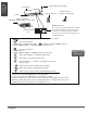
Step 4: Prepare refrigerant piping The refrigerant piping is inside an insulating sleeve attached to the back of the unit. You must prepare the piping before passing it through the hole in the wall. 1. Based on the position of the wall hole relative to the mounting plate, choose the side from which the piping will exit the unit. 2. If the wall hole is behind the unit, keep the knock-out panel in place.
BEFORE PERFORMING ANY ELECTRICAL WORK, READ THESE REGULATIONS BEFORE PERFORMING ANY ELECTRICAL OR WIRING WORK, TURN OFF THE MAIN POWER TO THE SYSTEM. Step 6: Connect signal cable The signal cable enables communication between the indoor and outdoor units. You must first choose the right cable size before preparing it for connection.
1. Open front panel of the indoor unit. 2. Using a screwdriver, open the wire box cover on the right side of the unit. This will reveal the terminal block. Terminal block Wire cover Screw Cable clamp WARNING NOTE ABOUT WIRING THE WIRING CONNECTION PROCESS MAY DIFFER SLIGHTLY BETWEEN UNITS AND REGIONS.
Step 8: Mount indoor unit If you installed new connective piping to the outdoor unit, do the following: 1. If you have already passed the refrigerant 2. 3. 4. 5. 6. 7. piping through the hole in the wall, proceed to Step 4. Otherwise, double-check that the ends of the refrigerant pipes are sealed to prevent dirt or foreign materials from entering the pipes. Slowly pass the wrapped bundle of refrigerant pipes, drain hose, and signal wire through the hole in the wall.
Outdoor Unit Installation 60cm (24in) above Install the unit by following local codes and regulations , they may differ slightly between different regions. " 2 4" ed 1 m d mu en all nu m Mi com ck w a Re m b o fr ! NOTE Minimum clearance shown will incur minor efficiency and capacity loss typically 5% to 7%.
Step 3: Anchor outdoor unit The outdoor unit can be anchored to the ground or to a wall-mounted bracket with bolt(M10). Prepare the installation base of the unit according to the dimensions below. UNIT MOUNTING DIMENSIONS The following is a list of different outdoor unit sizes and the distance between their mounting feet. Prepare the installation base of the unit according to the dimensions below.
Outdoor Unit Dimensions (in) WxHxD Mounting Dimensions Distance A (in) Distance B (in) 26.8”x17.1”x11.2” 18.1” 11.5” 27.5”x21.6”x10.6” 17.7” 10.2” 27.5”x21.6”x10.8” 17.7” 10.2” 28.3”x19.5”x10.6” 17.7” 10.0” 28.7”x21.8”x11.8” 17.8” 11.9” 30.12”x21.8”x11.9” 17.8” 11.3” 30.3”x21.8”x11.8” 19.2” 11.7” 31.7”x21.8”x12.9” 20.1” 12.5” 31.5”x21.8”x13.1” 20.2” 13.4” 33.3”x27.6”x14.3” 21.3” 13.8” 35.0”x26.5”x13.5” 26.1” 13.9” 37.2”x31.9”x16.5” 26.5” 15.9” 37.2”x31.9”x16.1” 26.
Step 4: Connect signal and power cables The outside unit’s terminal block is protected by an electrical wiring cover on the side of the unit. A comprehensive wiring diagram is printed on the inside of the wiring cover. WARNING BEFORE PERFORMING ANY ELECTRICAL OR WIRING WORK, TURN OFF THE MAIN POWER TO THE SYSTEM. 1.
Refrigerant Piping Connection When connecting refrigerant piping, do not let substances or gases other than the specified refrigerant enter the unit. The presence of other gases or substances will lower the unit’s capacity, and can cause abnormally high pressure in the refrigeration cycle. This can cause explosion and injury. Note on Pipe Length The length of refrigerant piping will affect the performance and energy efficiency of the unit.
Step 2: Remove burrs Burrs can affect the air-tight seal of refrigerant piping connection. They must be completely removed. 1. Hold the pipe at a downward angle to prevent burrs from falling into the pipe. 2. Using a reamer or deburring tool, remove all burrs from the cut section of the pipe. Pipe Reamer Point down PIPING EXTENSION BEYOND FLARE FORM Outer Diameter of Pipe (mm) A (mm) Min. Max. Max. Ø 6.35 (Ø 0.25”) 0.7 (0.0275”) 1.3 (0.05”) Ø 9.52 (Ø 0.375”) 1.0 (0.04”) 1.6 (0.063”) Ø12.7 ( Ø 0.
2. Tighten the flare nut as tightly as possible by hand. 3. Using a crescent wrench, grip the nut on the unit tubing. 4. While firmly gripping the nut on the unit tubing, use a torque wrench to tighten the flare nut according to the torque values in the Torque Requirements table below. Loosen the flaring nut slightly, then tighten again. TORQUE REQUIREMENTS Outer Diameter of Pipe (mm) Tightening Torque (N•m) Ø 6.35 (Ø 0.25”) 18~20(180~200kgf.cm) 8.4~8.7 (0.33~0.34”) Ø 9.52 (Ø 0.
Air Evacuation If there is a change in system pressure, refer to Gas Leak Check section for information Air and foreign matter in the refrigerant circuit can on how to check for leaks. If there is no change in system pressure, unscrew the cap cause abnormal rises in pressure, which can damage the air conditioner, reduce its efficiency, and cause 9. from the packed valve (high pressure valve). Insert hexagonal wrench into the packed valve injury.
Note on Adding Refrigerant Some systems require additional charging depending on pipe lengths. The standard pipe length varies according to local regulations. For example, in North America, the standard pipe length is 7.5m (25’). In other areas, the standard pipe length is 5m (16‘). The refrigerant should be charged from the service port on the outdoor unit’s low pressure valve.
Electrical and Gas Leak Checks Before Test Run Only perform test run after you have completed the following steps: • Electrical Safety Checks – Confirm that the unit’s electrical system is safe and operating properly • Gas Leak Checks – Check all flare nut connections and confirm that the system is not leaking • Confirm that gas and liquid (high and low pressure) valves are fully open Electrical Safety Checks After installation, confirm that all electrical wiring is installed in accordance with local and n
Test Run Test Run Instructions You should perform the Test Run for at least 30 minutes. 1. Connect power to the unit. 2. Press the ON/OFF button on the remote controller to turn it on. 3. Press the MODE button to scroll through the following functions, one at a time: • COOL – Select lowest possible temperature • HEAT – Select highest possible temperature 4.
Impedance Information (Applicable to following models only) This appliance MST2ABD-18CR-QB9 can be connected only to a supply with system impedance no more than 0.163Ω. In case necessary, please consult your supply authority for system impedance information. This appliance MST2ABE-22CR-QB9 can be connected only to a supply with system impedance no more than 0.186Ω. In case necessary, please consult your supply authority for system impedance information.
LIMITED EXPRESS WARRANTY Congratulations on purchasing your new HVAC equipment. It’s been designed for long life and reliable service, and is backed by one of the strongest warranties in the industry. Your unit automatically qualifies for the warranty coverage listed below, providing you keep your proof of purchase (receipt) for the equipment and meet the warranty conditions.
THIS PAGE IS INTENTIONALLY LEFT BLANK
THIS PAGE IS INTENTIONALLY LEFT BLANK
THIS PAGE IS INTENTIONALLY LEFT BLANK
'XH WR RQJRLQJ SURGXFW LPSURYHPHQWV VSHFLILFDWLRQV DQG GLPHQVLRQV DUH VXEMHFW WR FKDQJH DQG FRUUHFWLRQ ZLWKRXW QRWLFH RU LQFXUULQJ REOLJDWLRQV 'HWHUPLQLQJ WKH DSSOLFDWLRQ DQG VXLWDELOLW\ IRU XVH RI DQ\ SURGXFW LV WKH UHVSRQVLELOLW\ RI WKH LQVWDOOHU $GGLWLRQDOO\ WKH LQVWDOOHU LV UHVSRQVLEOH IRU YHULI\LQJ GLPHQVLRQDO GDWD RQ WKH DFWXDO SURGXFW SULRU WR EHJLQQLQJ DQ\ LQVWDOODWLRQ SUHSDUDWLRQV ,QFHQWLYH DQG UHEDWH SURJUDPV KDYH SUHFLVH UHTXLUHPHQWV DV WR SURGXFW SHUIRUPDQFH DQG FHUWLILFDWLRQ $OO SUR