INSTALLATION , OPERATION & MAINTENANCE MANUAL Horizontal/Side Discharge Condensing Units Models CMA12SD-0 CMA18SD-1 CMA24SD-1 CMA30SD-1 CMA36SD-1 CMA48SD-1 517.787.2100 • www.marsdelivers.
Owner’s Manual - CMA12-48SD Horizontal/Side Discharge Condensing Units: Installation, Operation and Maintenance TABLE OF CONTENTS Safety Precautions ................................................................................................................... 3 General Operating Instructions................................................................................................. 4 General Product Information .....................................................................................
Owner’s Manual - CMA12-48SD SAFETY PRECAUTIONS Please read this installation manual completely before installing the product. If the power cord is damaged, replacement work shall be performed by authorized personnel only. Installation work must be performed in accordance with all local and national codes by authorized personnel only. Contact an authorized service technician for repair, maintenance or installation of this unit.
Owner’s Manual - CMA12-48SD OPERATING INSTRUCTIONS IMPORTANT Air conditioners are designed to provide comfort cooling at outside temperatures above 65°F (18°C) but less than 109°F (43°C). Operating the air conditioner outside of this temperature range may cause unit failure and will void the warranty. If you have need for cooling at lower outdoor temperatures a “low ambient cooling kit” can be field installed. Contact your local contractor or call the factory.
Owner’s Manual - CMA12-48SD GENERAL PRODUCT INFORMATION UNPACKING AND INSPECTION: THERMOSTAT AND INDOOR FAN TIME DELAY: The condensing unit is shipped completely assembled and in it’s own package. All goods are inspected at the factory and released to the freight company in good condition. When received at the site, a visual inspection of all packages should be made immediately.
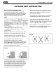
Owner’s Manual - CMA12-48SD OUTDOOR UNIT INSTALLATION UNIT LOCATION AND MOUNTING: An awning can be built over the outdoor unit to prevent direct sunlight or rain exposure or snowfall. Ensure that the awning is at least 2 ft. above the top of the unit’s housing. Choose a location that places the condensing unit as close to the indoor unit as possible. The maximum unit separation and vertical lift (compressor above evaporator) must be taken into account [See Fig 1]. Do not exceed allowable pipe lengths.
Owner’s Manual - CMA12-48SD OUTDOOR UNIT INSTALLATION continued 1. Split type outdoor unit clearances Clearances Fig. 4 LQFK 1. Ensure that there is sufficient clearance around the unit for installation and maintenance. Clearance must be maintained to ensure that the air inlets and outlets are not obstructed. [See Fig. 4]. LQFK Anchor the outdoor unit with a 10mm (3/8 inch) diameter bolt and nut tightly on a concrete or rigid surface [See Fig. 5].
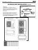
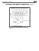
Owner’s Manual - CMA12-48SD UNIT WIRING Outdoor unit wiring connection ELECTRICAL WIRING AND SUPPLY VOLTAGE: 1. Remove the electrical control cover from the outdoor unit. All electrical wiring must be done according to NEC and local codes. Nameplate data indicates the operating voltage, phase, ampacity, maximum over current protection, and minimum voltage. 2.
Owner’s Manual - CMA12-48SD OUTDOOR UNIT WIRING CONNECTION TERMINAL bLOCk OF OUTDOOR UNIT *NOTE: Please refer to the installation instructions of the 24V thermostat used in conjunction with this unit for additional wiring instructions.
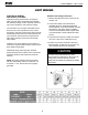
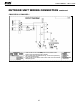
Owner’s Manual - CMA12-48SD OUTDOOR UNIT WIRING CONNECTION continued CMA12SD-0 & CMA18SD-1 1. Units should use an unattached power switch, stated-crosssection wires and matching-spec. breaker. 2. Use the fuse within the specified scope, it cannot be replaced by iron wires or brass wires. 3. Units should use the stated-cross-section earth wire and maintain adequate ground.
Owner’s Manual - CMA12-48SD OUTDOOR UNIT WIRING CONNECTION continued CMA24SD-1 & CMA30SD-1 1. Units should use an unattached power switch, stated-crosssection wires and matching-spec. breaker. 2. Use the fuse within the specified scope, it cannot be replaced by iron wires or brass wires. 3. Units should use the stated-cross-section earth wire and maintain adequate ground.
Owner’s Manual - CMA12-48SD OUTDOOR UNIT WIRING CONNECTION continued CMA36SD-1 & CMA48SD-1 1. Units should use an unattached power switch, stated-crosssection wires and matching-spec. breaker. 2. Use the fuse within the specified scope, it cannot be replaced by iron wires or brass wires. 3. Units should use the stated-cross-section earth wire and maintain adequate ground.
Owner’s Manual - CMA12-48SD REFRIGERANT PIPING LEAk TEST, EVACUATION & RELEASE OF REFRIGERANT The length of refrigerant lines and the number of bends determine the pressure drop which affects capacity and efficiency of the system and oil return to the compressor. The outdoor unit connections are flare type. Tube size should always be the same diameter as the connections provided at the service valves.
Owner’s Manual - CMA12-48SD INITIAL START-UP & CHECkS FINAL INSPECTION Operation of the unit is automatic and will provide cooling depending on the setting of the thermostat. Do a final visual inspection of the entire installation and complete any final details and clean up. IMPORTANT! All panels must be installed, main power turned on and the thermostat properly connected before operating the unit. Review Unit Operation with the homeowner/user.
Owner’s Manual - CMA12-48SD THIS PAGE INTENTIONALLY LEFT BLANK.
'XH WR RQJRLQJ SURGXFW LPSURYHPHQWV VSHFLILFDWLRQV DQG GLPHQVLRQV DUH VXEMHFW WR FKDQJH DQG FRUUHFWLRQ ZLWKRXW QRWLFH RU LQFXUULQJ REOLJDWLRQV 'HWHUPLQLQJ WKH DSSOLFDWLRQ DQG VXLWDELOLW\ IRU XVH RI DQ\ SURGXFW LV WKH UHVSRQVLELOLW\ RI WKH LQVWDOOHU $GGLWLRQDOO\ WKH LQVWDOOHU LV UHVSRQVLEOH IRU YHULI\LQJ GLPHQVLRQDO GDWD RQ WKH DFWXDO SURGXFW SULRU WR EHJLQQLQJ DQ\ LQVWDOODWLRQ SUHSDUDWLRQV ,QFHQWLYH DQG UHEDWH SURJUDPV KDYH SUHFLVH UHTXLUHPHQWV DV WR SURGXFW SHUIRUPDQFH DQG FHUWLILFDWLRQ $OO SUR