
User Guide


IOM - Horizontal/Side Discharge Condensing Units
13
13
Horizontal/Side Discharge Condensing Units
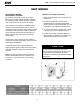
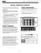
The length of refrigerant lines and the number of
bends determine the pressure drop which affects
capacity and efficiency of the system and oil
return to the compressor. Tube size should always
be the same diameter as the connections
provided at the service valves. Up sizing of lines
can result in inadequate oil return to the
compressor and excessive refrigerant charge and
will void the warranty [See Table 1].
REFRIGERANT PIPING
LEAk TEST,
EVACUATION
& RELEASE OF
REFRIGERANT
The condensing unit is supplied with R-410a
charge sufcient for most matching evaporator
units. Charge must be added for interconnecting
tubing.
The unit’s service valves are shipped in the closed
position and should not be opened until nal
connections and evacuation are completed.
The recommended procedure for leak test,
evacuation, and release of refrigerant is
outlined below:
1. Complete the final piping connections to the
indoor and outdoor units using high temperature
brazing alloy.
2. Connect a charging manifold to the service ports
provided at the service valves.
3. Pressurize the lines and evaporator with nitrogen
and leak check all connections with soap
bubbles. Repair as necessary any
faulty joints. If brazing is required be sure to
RELEASE THE NITROGEN FIRST. Re-test as
needed.
4. Connect a vacuum pump to the manifold center
connection, start the pump and open the
manifold valves.
5. Evacuate to 500 microns or less for a minimum
of 30 minutes. Close the manifold valves and
shut off the pump. Note the vacuum reading and
wait 15 minutes. Take a new vacuum reading. A
reading of 800 microns or higher indicates the
presence of moisture or a leak.
6. Repair as necessary and repeat steps 3, 4 & 5.
7. Confirm that manifold valves are closed and
disconnect the vacuum pump.
8. Remove the caps from the service valves. Open
the valves to the fully ‘back-seat’ position.
Replace service valve caps and tighten.
WARNING
It is illegal to discharge refrigerant into the
atmosphere. Use proper reclaiming methods
and equipment when working on the refrigerant
containing parts of the unit. Service should be
performed by a QUALIFIED service agency and
certied technicians.
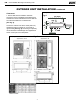
*Minimum pipe length 15 feet.
** “P” trap risers every 10 ft. when outdoor unit is installed
above indoor unit.
Choose a location that places the condensing
unit as close to the indoor unit as possible. The
maximum separation is dependent on model.
Use only clean refrigeration grade tubing. Avoid
piping on wet or rainy days. Always keep the tube
ends capped until you are ready to make the nal
connections. Remove burrs from cut ends of tubing.
Use tube benders to avoid kinking.
Insulate the suction line with Armaflex or equivalent
with a wall thickness of at least 1/2”. Support the
tubing adequately to avoid sags that can trap oil.
Isolate the tubing so as not to transmit noise to the
building structure. Avoid sharp edges that could cut
the tubes. Maximum vertical lift (compressor above
evaporator) is dependent on model. Trap risers with
a ‘P’ trap every 10 feet.
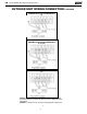
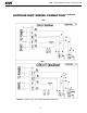
CMA12 CMA24
CMA36
CMA18 CMA30
CMA48