
User Guide


Owner’s Manual - B-VMH18,24UU-1
2
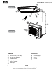
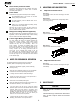
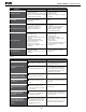
INDOOR UNIT
OUTDOOR UNIT
1
2
3
4
5
6
7
8
9
Connecting pipe
Air inlet
Air outlet
Air flow louver (at air outlet)
Air inlet (with air filter in)
Installation part
Display panel
Remote controller
Drain pipe
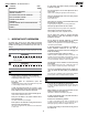
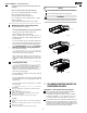
INDOOR UNIT
OUTDOOR UNIT
1
2
3
5
4
7
6
8
8
9
All the pictures in this manual are for explanation purpose only. They may be slightly different from the air
conditioner you purchased(depend on model). The actual shape shall prevail.
NOTE
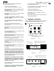
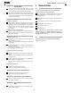
RESET
TIME ON
TIME OFF
CLOCK
SWING
AIR DIREC TION
OK
ECO
SWING
MODE
FAN
SPEED
M
LOCK
C/H
AUTO
COOL
DRY
HEAT
FAN
TEMP
SET
CLOCK
SET
HOUR
FAN SPEED