INSTALLATION MANUAL Ceiling and Floor Unit Models B-VMH18UU-1 B-VMH24UU-1 517.787.2100 • www.marsdelivers.
Installation Manual - B-VMH18,24UU-1 CONTENTS Install strictly according to this installation instruction. If installation is defective, it will cause water leakage, electrical shock and fire. PAGE PRECAUTIONS.......................................................................................2 INSTALLATION INFORMATION...............................................................
Installation Manual - B-VMH18,24UU-1 The temperature of refrigerant circuit will be high, please keep the interconnection cable away from the copper tube. The appliance shall be installed in accordance with national wiring regulations. Do not operate your air conditioner in a wet room such as a bathroom or laundry room. After completing the installation work, check that the refrigerant does not leak.
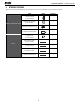
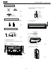
Installation Manual - B-VMH18,24UU-1 3. ATTACHED FITTINGS Please check whether the following fittings are of full scope. If there are some spare fittings , please restore them carefully. NAME Remote controller & Its Holder Others SHAPE QUANTITY 1. Remote controller (on some models) 1 2. Remote controller holder (on some models) 1 3. Mounting screw(ST2.9×10-C-H) 2 4. Alkaline dry batteries (AM4) 2 5. Magnetic ring (on some models) 2 6.
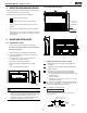
Installation Manual - B-VMH18,24UU-1 4. 5.2 Install the main body INSPECTING AND HANDLING THE UNIT At delivery, the package should be checked and any damage should be reported immediately to the the service agent. When handling the unit, take into account the following: B Fragile, handle the unit with care. 1 Keep the unit upright in order to avoid compressor damage. 2 Choose beforehand the path along which the unit is to be brought in.
Installation Manual - B-VMH18,24UU-1 NEW CONCRETE BRICKS Inlaying or embedding the screw bolts. (Slide insertion) 20~25mm (Blade shape insertion) Locate the hanging arm on the hanging screw bolt. (Refer to Fig. 5-9) Fig.5-4 Screw nut Washer Steel bar Hanging screw bolt Embedding screw bolt (Pipe hanging and embedding screw bolt) Fig.5-5 Hanging arm Fig.
Installation Manual - B-VMH18,24UU-1 6. OUTDOOR UNIT INSTALLATION The area must be free of combustible gases and chemicals. Outdoor Unit Installation Instructions Step 1: Select installation location. The pipe length between the outdoor and indoor unit may not exceed the maximum allowable pipe length. The outdoor unit should be installed in a location that meets the following requirements: If possible, DO NOT install the unit where it is exposed to direct sunlight.
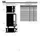
Installation Manual - B-VMH18,24UU-1 Split Type Outdoor Unit (Refer to Fig 6.4, 6.5, 6.6, 6.10 and Table 6.1) Table 6.1: Length Specifications of Split Type Outdoor Unit (unit: mm/inch) Outdoor Unit Dimensions WxHxD H Fig. 6.4 W W H Fig. 6.5 A D B Fig. 6.6 8 Mounting Dimensions Distance A Distance B 760x590x285 (29.9x23.2x11.2) 530 (20.85) 290 (11.4) 810x558x310 (31.9x22x12.2) 549 (21.6) 325 (12.8) 845x700x320 (33.27x27.5x12.6) 560 (22) 335 (13.2) 900x860x315 (35.4x33.85x12.
Installation Manual - B-VMH18,24UU-1 NOTE: Make sure the water drains to a safe location where it will not cause water damage or a slipping hazard. 60 cm / 2 3.6”above NOTE: The minimum distance between the outdoor unit and walls described in the installation guide does not apply to airtight rooms. Be sure to keep the unit unobstructed in at least two of the three directions (M, N, P) (See Fig. 6.10) 30 cm cm 30 om ”fr 1.8 /1 Base pan hole of outdoor unit ll wa ck ba Seal Seal / 11.
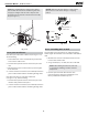
Installation Manual - B-VMH18,24UU-1 7. CONNECT THE DRAIN PIPE Install the drainpipe of the indoor unit The outlet has PTI screw bread, Please use sealing materials and pipe sheath(fitting) when connecting PVC pipes. CAUTION The drain pipe of indoor unit must be heat insulated, or it will condense dew, as well as the connections of the indoor unit. Hard PVC binder must be used for pipe connection, and make sure there is no leakage.
Installation Manual - B-VMH18,24UU-1 8. INSTALL THE CONNECTING PIPE Table 8.1: The Maximum Length And Drop Height Based on Models. (Unit: m/ft.) Safety Precautions Type of model Capacity (Btu/h) R410A Inverter Split Type ≥24K - <36 K 50/164 25/82 ≥36K - ≤60K 65/213 30/98.4 WARNING • All field piping must be completed by a licensed technician and must comply with the local and national regulations.
Installation Manual - B-VMH18,24UU-1 CAUTION CAUTION If the outdoor unit is installed higher than the indoor unit: • Oil traps If the indoor unit is installed higher than the outdoor unit: -It is recommended that vertical suction risers not be upsized. Proper oil return to the compressor should be maintained with suction gas velocity. If velocities drop below7.62m/s(1500fpm (feet per minute)), oil return will be decreased. An oil trap should be installed every 6m(20ft) of vertical suction line riser.
Installation Manual - B-VMH18,24UU-1 Refrigerant Piping Connection Instructions Step 2: Remove burrs. Burrs can affect the air-tight seal of refrigerant piping connections. They must be completely removed. CAUTION • The branching pipe must be installed horizontally. An angle of more than 10° may cause malfunction. DO NOT install the connecting pipe until both indoor and outdoor units have been installed. Insulate both the gas and liquid piping to prevent water leakage. • • 1.
Installation Manual - B-VMH18,24UU-1 6. Place flaring tool onto the form. 7. Turn the handle of the flaring tool clockwise until the pipe is fully flared. Flare the pipe in accordance with the dimensions shown in table 8.2. Table 8.2: PIPING EXTENSION BEYOND FLARE FORM Pipe gauge Tightening torque Flare dimension (A) (Unit: mm/Inch) Min. • Be sure to wrap insulation around the piping. Direct contact with the bare piping may result in burns or frostbite. • Make sure the pipe is properly connected.
Installation Manual - B-VMH18,24UU-1 9. AIR EVACUATION 8. Insert hexagonal wrench into the packed valve (high pressure valve) and open the valve by turning the wrench in a 1/4 counterclockwise turn. Listen for gas to exit the system, then close the valve after 5 seconds. Safety Precautions CAUTION Flare nut • Use a vacuum pump with a gauge reading lower than -0.1MPa and an air discharge capacity above 40L/min. • The outdoor unit does not need vacuuming.
Installation Manual - B-VMH18,24UU-1 10. WIRING 10.1 Connect the cable The appliance shall be installed in accordance with national wiring regulations. Remove the electric cover of the outdoor unit. If there is no cover on the outdoor unit, disassemble the bolts from the maintenance board and remove the protection board. (See Fig. 10.1) The air conditioner should use separate power supply with rated voltage.
Installation Manual - B-VMH18,24UU-1 11. TEST OPERATION 1 The test operation must be carried out after the entire installation has been completed. 2 Please confirm the following points before the test operation: The indoor unit and outdoor unit are installed properly. Tubing and wiring are correctly completed. The refrigerant pipe system is leakage-checked. The drainage is unimpeded. The heating insulation works well. The ground wiring is connected correctly.
Installation Manual - B-VMH18,24UU-1 The Specification of Power for the invert type air conditioner (independant power supply) Table 10-1 18 24 PHASE 1Phase 1Phase 1Phase VOLT 220-240 V 220-2 40V 220-2 40V 15/10 15/10 15/10 PHASE 1Phase 1Phase 1Phase VOLT 208-240 V 208-2 40V 208-2 40V 30/20 30/20 40/30 MODEL POWER (indoor) CIRCUIT BREAKER/FUSE(A) POWER (outdoor) CIRCUIT BREAKER/FUSE(A) 18 30~36
Installation Manual - B-VMH18,24UU-1 CAUTION The power supply is included in the power supply above mentioned can be applied to the table. Before obtaining access to terminals, all supply circuits must be disconnected. Wiring figure Fig.
'XH WR RQJRLQJ SURGXFW LPSURYHPHQWV VSHFLILFDWLRQV DQG GLPHQVLRQV DUH VXEMHFW WR FKDQJH DQG FRUUHFWLRQ ZLWKRXW QRWLFH RU LQFXUULQJ REOLJDWLRQV 'HWHUPLQLQJ WKH DSSOLFDWLRQ DQG VXLWDELOLW\ IRU XVH RI DQ\ SURGXFW LV WKH UHVSRQVLELOLW\ RI WKH LQVWDOOHU $GGLWLRQDOO\ WKH LQVWDOOHU LV UHVSRQVLEOH IRU YHULI\LQJ GLPHQVLRQDO GDWD RQ WKH DFWXDO SURGXFW SULRU WR EHJLQQLQJ DQ\ LQVWDOODWLRQ SUHSDUDWLRQV ,QFHQWLYH DQG UHEDWH SURJUDPV KDYH SUHFLVH UHTXLUHPHQWV DV WR SURGXFW SHUIRUPDQFH DQG FHUWLILFDWLRQ $OO SUR