
Install Instructions


Installation Manual - B-VMH09,12,18CU-1
11
3 INSTALL THE REFRIGERANT PIPE
Execute heat insulation work completely on both sides of the
gas piping and liquid piping. Otherwise, this can sometimes
result in water leakage.
(When using a heat pump, the temperature of the gas piping can
reach up to approximately 120℃/248 . Use insulation which is
sufficiently resistant.)
O
F
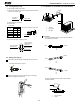
Before rigging tubes, check which type of refrigerant is used.
All field piping must be provided by a licensed refrigeration
technician and must comply with the relevant local and
national codes.
Use a pipe cutter and flare suitable for used refrigerant.
Do not mix anything other than the specified refrigerant, such
as air, etc.., Inside the refrigerant circuit.
If the refrigerant gas leaks during the work, ventilate the area.
A toxic gas is emitted by the refrigerant gas being exposed to
a fire.
Make sure there is no refrigerant gas leak. A toxic gas may be
released by the refrigerant gas leaking indoor and being
exposed to flames from an area heater, cooking stove, etc.
Also, in cases where the temperature and humidity of the
O
refrigerant piping sections might exceed 30℃/86 F or Rh80%,
reinforce the refrigerant insulation(20mm/0.8in or thicker).
Condensation may form on the surface of the insulating material.
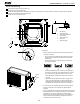
Only use annealed material for flare connections.
Precautions
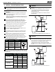
Refer to the table below for the dimensions of flare nuts spaces
and the appropriate tightening torque. (Over tightening may
damage the flare and cause leaks.)
Pipe gauge
(mm)
Tightening torque
Flare dimension
A (mm)
Flare shape
O
6.35(1/4 in)
18~20 N. m
(183~204 kgf.cm)
8.4~8.7
0.33~0.34in
13.2~13.5
0.52~0.53in
16.2~16.5
0.64~0.65in
19.2~19.7
0.76~0.78in
25~26 N. m
(255~265 kgf.cm)
35~36 N. m
(357~367 kgf.cm)
45~47 N. m
(459~480 kgf.cm)
O
9.52(3/8in)
O12.7(1/2in)
O15.9(5/8in)
R0.4~0.8
45
2
90
4
A
o
o
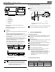
Check whether the height drop between the indoor unit and
outdoor unit, and the length of refrigerant pipe meet the following
requirements:
Capacity
(Btu/h)
The type of models
Max.allowable
piping length
49.2 ft/15m
82ft/25m
82ft/25m
82ft/25m
9K ~12K
9K ~12K
9K ~12K
9K ~12K
T1 condition
Split type air conditioner
R410A inverter
Split type air conditioner
T3 condition
(outdoor unit down)
T3 condition
(outdoor unit up)
Max.allowable
piping height
26.2ft/8m
32.8ft/10m
32.8ft/10m
49.2ft/15m
82ft/25m
98.4ft/30m
98.4ft/30m
98.4ft/30m
18K
18K
18K
18K
49.2ft/15m
65.6ft/20m
49.2ft/15m
65.6ft/20m
0.016~0.031in
CAUTION
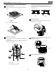
Oil traps
If the indoor unit is installed higher than the outdoor unit:
-If oil compressor, this might cause liquid compression
or deterioration of oil return. Oil traps in the rising gas
piping can prevent this.
An oil trap should be installed every 32.8ft(10m) of vertical
suction line riser.
The indoor unit is installed higher than the outdoor unit
CAUTION
If the outdoor unit is installed higher than the indoor unit:
-It is recommended that vertical suction risers not be up sized.
Proper oil return to the compressor should be maintained with
suction gas velocity. If velocities drop below 7.62m/s
(1500fpm [feet per minute]), oil return will be decreased.
An oil trap should be installed every 20ft(6m) of vertical suction
line riser.
The outdoor unit is installed higher than the indoor unit