
Install Instructions


Installation Manual - B-VMH09,12,18CU-1
15
5 ELECTRIC WIRING WORK
General instructions
- Gas pipes: might cause explosions or fire if gas leaks.
- Water pipes: no grounding effect if hard vinyl piping is used.
- Telephone ground wires or lightning rods: might cause
abnormally high electric potential in the ground during
lightning storms.
All field wiring and components must be installed by a licensed
electrician and must comply with relevant local and national
regulations.
Use copper wire only.
Follow the 'Wiring diagram' attached to the unit body to wire the
outdoor unit, indoor units and the remote controller.
A circuit breaker capable of shutting down power supply to the
entire system must be installed.
Note that the operation will restart automatically if the main
power supply is turned off and then turned back on again.
Be sure to ground the air conditioner.
Do not connect the ground wire to gas pipes, water pipes,
lightning rods, or telephone ground wires.
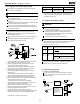
The specification of power
Phase
Volt
Circuit breaker/Fuse(A)
9K~18K
1Phase 208-240V
20/16
Model
Power
When electric wiring work is finished, check drainage flow during
COOL running, explained in "Test operation" on page 18.
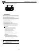
Add approximately 1L of water gradually through the air discharge
outlet.
Method of adding water (see the figure below)
4.4 Testing of drain piping
After the piping work is finished, check that drainage flows smoothly.
1
2
Plastic watering can(tube should be about 3.9 in/100 mm long)
Water-receiver
12
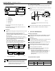
≥100/3.9in
Fresh air intake (φ65/2.6in)
106/4.2in
106/4.2in
75/3in
65/2.6in
Unit: mm
- Connect the drain hose to the drain raising pipes, and
insulate them.
- Connect the drain hose to the drain outlet on the indoor unit,
and tighten it with the clamp.
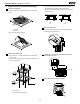
4.3 How to perform piping
Precautions
- Install the drain raising pipes at a height of less than 20.9 in/530
mm.
- Install the drain raising pipes at a right angle to the indoor
unit and no more than 11.8 in/300 mm from the unit.
- To prevent air bubbles, install the drain hose level or slightly tilted
up (3 in/<75 mm).
- The incline of drain hose should be 3 in/75 mm in or less so
that the drain socket does not have to withstand additional force.
- To ensure a downward slope of 1:100, install hanging
bars every 3.3ft/1m to 4.9ft/1.5m.
- When unifying multiple drain pipes, install the pipes as
shown in figure below. Select converging drain pipes whose
gauge is suitable for the operating capacity of the unit.
1 Ceiling slab
2 Hanger bracket
3 Adjustable range
4 Drain raising pipe
5 Drain hose
6 Metal clamp
1 T-joint converging drain pipes
0-530
100
1
1
Drain piping connections
Do not connect the drain piping directly to sewage
pipes that smell of ammonia. The ammonia in the
sewage might enter the indoor unit through the drain
pipes and corrode the heat exchanger.
Unit: mm
Unit: mm
1
2
0~75
5
1~1.5m
≤300/11.8in
6
5
4
3
220/8.7in
≤750/29.5in
0~3in
≤530/20.9in
3~5ft