INSTALLATION MANUAL Four-Way Cassette Model B-VMH09CU-1 B-VMH12CU-1 B-VMH18CU-1 517.787.2100 • www.marsdelivers.
Installation Manual - B-VMH09,12,18CU-1 If used as MULTI unit, please refer to the Installation & operation manuals packed with outdoor unit.
Installation Manual - B-VMH09,12,18CU-1 CONTENTS Install according to these installation instructions strictly. If installation is defective, it will cause water leakage, electrical shock and fire. Page PRECAUTIONS...................................................................................3 INSTALLATION INFORMATION..........................................................
Installation Manual - B-VMH09,12,18CU-1 If the refrigerant leaks during installation, ventilate the area immediately. Toxic gas may be produced if the refrigerant comes into contact with fire. There are flammable materials or gas. There is acid or alkaline liquid evaporating. Other special conditions. The temperature of refrigerant circuit will be high, please keep the interconnection cable away from the copper tube. After completing the installation work, check that the refrigerant does not leak.
Installation Manual - B-VMH09,12,18CU-1 ACCESSORIES For the following items, take special care during construction and check after installation is finished Check that the following accessories are included with your unit. 1 2 1X 2X 3 1X Tick√ when checked 4 2X Is the indoor unit fixed firmly? The unit may drop,vibrate or make noise. Is the gas leak test completed? It may result in insufficient cooling or heating. 5 6 1X+1X+1X 1X Is the unit fully insulated? Condensate water may drip.
Selecting installation site When the conditions in the ceiling are exceeding 300C / 860F and a relative humidity of 80%, or when fresh air is inducted into the ceiling, additional insulation is required (minimum 10 mm / 0.4in thickness, polyethylene foam). 1) - - - Where optimum air distribution can be ensured. Where nothing blocks air passage. Where condensate water can be properly drained. Where the false ceiling is not noticeably on an incline.
Installation Manual - B-VMH09,12,18CU-1 1.2 Relation of ceiling opening to unit and suspension bolt position. 5 4 1 2 Make the ceiling opening needed for installation where applicable.(For existing ceilings.) 570/22.4in 3 647/25.5in - Create the ceiling opening required for installation.From the side of the opening to the casing outlet, implement the refrigerant and drain piping and wiring for remote controller (unnecessary for wireless type). Refer to each piping or wiring section.
Installation Manual - B-VMH09,12,18CU-1 1.3 4) Check if the unit is horizontally levelled. Install the indoor unit - Do not install the unit tilted. The indoor unit is equipped with a built-in drain pump and float switch. (If the unit is tilted against the direction of the condensate flow (the drain piping side is raised), the float switch may malfunction and cause water to drip.) - Check if the unit is levelled at all four corners with a water level or a water-filled vinyl tube as shown in figure below.
Installation Manual - B-VMH09,12,18CU-1 OUTDOOR UNIT INSTALLATION 2.1 Precautions for selecting the location 1) Choose a place solid enough to bear the weight and vibration of the unit, where the operation noise will not be amplified. 2) Choose a location where the hot air discharged from the unit or the operation noise will not cause a nuisance to the neighbors of the user. 3) Avoid places near a bedroom and the like, so that the operation noise will cause no trouble.
Installation Manual - B-VMH09,12,18CU-1 2.4 Outdoor unit installation 2.3 Installation guidelines Where a wall or other obstacle is in the path of outdoor unit's inlet or outlet airflow, follow the installation guidelines below. 1) Installing outdoor unit When installing the outdoor unit, refer to "Precautions for selecting the location" . For any of the below installation patterns, the wall height on the outlet side should be 47.2 in/1200 mm or less.
Installation Manual - B-VMH09,12,18CU-1 3 INSTALL THE REFRIGERANT PIPE CAUTION All field piping must be provided by a licensed refrigeration technician and must comply with the relevant local and national codes. Precautions Execute heat insulation work completely on both sides of the gas piping and liquid piping. Otherwise, this can sometimes result in water leakage. (When using a heat pump, the temperature of the gas piping can reach up to approximately 120℃/248OF.
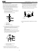
Installation Manual - B-VMH09,12,18CU-1 3.1 Flaring the pipe end 3.3 Installation of the throttle. (For some models) 1) Cut the pipe end with a pipe cutter. 2) Remove burrs with the cut surface facing downward so that the chips do not enter the pipe. Cut exactly at right angles. 00m .7in/5 ≥9 1 Remove burrs. 2 3 3) Put the flare nut on the pipe. 4) Flare the pipe. (in=mm/25.4) Max. Min. O6.35 (1/4 in) 1.3 0.7 O9.52 (3/8in) 1.6 1.0 O12.7 (1/2in) 1.8 1.0 O15.9 (5/8in) 2.2 2.
Installation Manual - B-VMH09,12,18CU-1 3.4 Purging air and checking gas leakage When piping work is completed, it is necessary to purge the air and check for gas leakage. Pipe length Up to 15m/49.2ft Run time Not less than 10 min More than 15m/49.2ft Not less than 15min *2. If the compound pressure gauge pointer swings back, refrigerant may have water content or a loose pipe joint may exist. Check all pipe joints and relighted nuts as needed, then repeat steps 2) through 4).
Installation Manual - B-VMH09,12,18CU-1 2) Be sure to insulate both the gas and liquid piping. Use separate thermal insulation pipes for gas and liquid refrigerant pipes. See the figure below. 4 4.1 Installation of drain piping Install the drain piping as shown in figure below and take measures against condensation. Improperly rigged piping could lead to leaks and eventually wet furniture and belongings.
Installation Manual - B-VMH09,12,18CU-1 4.3 How to perform piping 4.4 Testing of drain piping 2 75/3in Unit: mm 1 2 3 4 5 6 Ceiling slab Hanger bracket Adjustable range Drain raising pipe Drain hose Metal clamp 106/4.2in 4 106/4.2in 65/2.6in ≥100/3.9in 6 5 Add approximately 1L of water gradually through the air discharge outlet. Method of adding water (see the figure below) ≤750/29.5in 3 220/8.7in ≤530/20.9in 0~75 0~3in ≤300/11.
Installation Manual - B-VMH09,12,18CU-1 How to connect wiring Remove the control box lid of the indoor unit. Remove the cover of the outdoor unit. Follow the "Wiring diagram label" attached to the indoor unit's control box lid to wire the outdoor unit, indoor unit and the remote controller. Securely fix the wires with a field supplied clamp. Attach the cover of the outdoor unit.
Installation Manual - B-VMH09,12,18CU-1 6 INSTALLATION OF THE DECORATION PANEL - After installing the decoration panel, ensure that there is no space between the unit body and decoration panel. Otherwise air may leak through the gap and cause dewdrop. (See figure below) Detach the intake grille. - Slide the 2 grille hooks toward the middle of the decoration panel. 1 × 2 1 2 √ Mount the intake grille.
Installation Manual - B-VMH09,12,18CU-1 Close the intake grille, and close the 2 grille hooks. 7 TEST OPERATION Make sure the control box lids are closed on the indoor and outdoor units. Refer to ''For the following items, take special care during construction and check after installation is finished'' on page 2. After finishing the construction of refrigerant piping, drain piping, and electric wiring, conduct test operation accordingly to protect the unit.
Installation Manual - B-VMH09,12,18CU-1 THIS PAGE INTENTIONALLY LEFT BLANK.
'XH WR RQJRLQJ SURGXFW LPSURYHPHQWV VSHFLILFDWLRQV DQG GLPHQVLRQV DUH VXEMHFW WR FKDQJH DQG FRUUHFWLRQ ZLWKRXW QRWLFH RU LQFXUULQJ REOLJDWLRQV 'HWHUPLQLQJ WKH DSSOLFDWLRQ DQG VXLWDELOLW\ IRU XVH RI DQ\ SURGXFW LV WKH UHVSRQVLELOLW\ RI WKH LQVWDOOHU $GGLWLRQDOO\ WKH LQVWDOOHU LV UHVSRQVLEOH IRU YHULI\LQJ GLPHQVLRQDO GDWD RQ WKH DFWXDO SURGXFW SULRU WR EHJLQQLQJ DQ\ LQVWDOODWLRQ SUHSDUDWLRQV ,QFHQWLYH DQG UHEDWH SURJUDPV KDYH SUHFLVH UHTXLUHPHQWV DV WR SURGXFW SHUIRUPDQFH DQG FHUWLILFDWLRQ $OO SUR