
Install Instructions


Installation Manual - B-VMH18,24UU-1
15
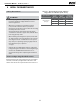
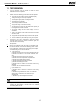
The outdoor unit is factory charged with refrigerant. Calculate
the added refrigerant according to the diameter and the
length of the liquid side pipe of the outdoor unit/indoor unit
connection.(suitable for throttle outdoor unit)
Table 9-1
Liquid tube(mm) R410A
1/4"
3/8"
0.011kg/m×(L-5)
0.030kg/m×(L-5)
orifice in the
outdoor unit
orifice in the
outdoor unit
9. AIR EVACUATION
Safety Precautions
CAUTION
• Use a vacuum pump with a gauge reading lower
than -0.1MPa and an air discharge capacity above
40L/min.
• The outdoor unit does not need vacuuming. DO
NOT open the outdoor unit ’s gas and liquid stop
valves.
• Ensure that the Compound Meter reads -0.1MPa
or below after 2 hours. If after three hours of
operation and the gauge reading is still above
-0.1MPa, check if there is a gas leak or water inside
the pipe. If there is no leakage, perform another
evacuation for 1 or 2 hours.
• DO NOT use refrigerant gas to evacuate the system.
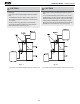
Evacuation Instructions
Before using manifold gauge and vacuum pump, read their
operation manuals to familiarize yourself with how to use
them properly.
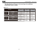
Manifold Gauge
Compound gauge
-76cmHg
Low pressure valve
High pressure valve
Charge hose
Charge hose
Vacuum pump
Pressure gauge
Low pressure valve
Fig. 9.1
1. Connect the charge hose of the manifold gauge to
service port on the outdoor unit’s low pressure valve.
2. Connect another charge hose from the manifold gauge
to the vacuum pump.
3. Open the Low Pressure side of the manifold gauge.
Keep the High Pressure side closed.
4. Turn on the vacuum pump to evacuate the system.
5. Run the vacuum for at least 15 minutes, or until the
Compound Meter reads -76cmHG (-1x10⁵Pa).
6. Close the Low Pressure side of the manifold gauge, and
turn o the vacuum pump.
7. Wait for 5 minutes, then check that there has been no
change in system pressure.
NOTE:
The table above refers to the liquid tube.
The number of bends is up to the length of the max height drop.
Usually for each 32 ft need a bend.
If a negative result is gotten for R from Table 9-1, no refrigerant
needs to be added nor removed.
NOTE: If there is no change in system pressure, unscrew
the cap from the packed valve (high pressure valve). If
there is a change in system pressure, there may be a gas
leak.
Note On Adding Refrigerant
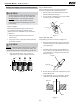
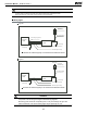
8. Insert hexagonal wrench into the packed valve (high
pressure valve) and open the valve by turning the
wrench in a 1/4 counterclockwise turn. Listen for gas to
exit the system, then close the valve after 5 seconds.
Flare nut
Cap
Valve body
Valve stem
Fig. 9.2
Watch the Pressure Gauge for one minute to make sure
there is no change in pressure. The Pressure Gauge
should read slightly higher than atmospheric pressure.
Remove the charge hose from the service port.
Using hexagonal wrench, fully open both the high
pressure and low pressure valves.
OPEN VALVE STEMS GENTLY
When opening valve stems, turn the hexagonal wrench
until it hits against the stopper. DO NOT try to force the
valve to open further.
12. Tighten valve caps by hand, then tighten it using the
9.
10.
11.
proper tool.
CAUTION
• Refrigerant charging must be performed after
wiring, vacuuming and the leak test.
• DO NOT exceed the maximum allowable quantity
of refrigerant or ove rcharge the system. Doing so
can damage or impact the unit ’s function.
• Charging with unsuitable substances may cause
explosions or accidents. Ensure that the appropriate
refrigerant is used.
• Refrigerant containers must be opened slowly.
Always use protective gear when charging the system.
• DO NOT mix refrigerants types.