
Install Instructions


7
B-VFH—UA-1 InverterFlex
®
Multi-Zone Floor & Ceiling Type Indoor Unit Heat Controller
3 Installation of Floor and Ceiling Type Indoor Unit
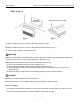
3.1 Space Dimension for Unit Installation
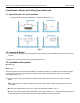
The space around the unit is adequate for ventilation. (Refer to Fig. 1)
3.2 Important Notice
(1). The unit must be installed by professional personnel according to this installation manual to ensure proper
function.
(2). Relocation should be performed by professional personnel.
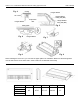
3.3 Installation Description
n Ceiling type
n Floor type
These two types of units have similar installation procedures as follows: (1). Determine the mounting position
on ceiling or wall by using paper pattern to indicate indoor frame. Mark the pattern and pull out the paper
pattern.(Refer to Fig. 2).
(2). Remove the return grill, the side panel and the hanger bracket from the indoor unit as per procedure
below.
n Press the xing knob of the air intake grills, the grilles will be opened wider and then pull them out from
the indoor.
n Loosen the side panel xing screw and remove the side panel. (Refer to Fig. 3).
n Loosen two hanger bracket setting bolts (M8) on each side for less than .5”. Remove two hanger bracket
xing bolts (M6) on the rear side. Detach the hanger bracket by pulling it backward.
>36”
>36”
>5 ft.
>24”
>24”
>40”
>6”
>7.5 ft.
>5 ft.
>12”
>1 ft.
Fig. 1