
Install Instructions

12
Heat Controller B-VFH—UA-1 InverterFlex
®
Multi-Zone Floor & Ceiling Type Indoor Unit
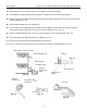
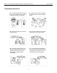
n Either the right rear or right side of the unit is suitable for xing the drainpipe.
n The diameter of the drainpipe should be equal to or greater than that of the connecting pipe.
n Make the drainpipe as short as possible and slope downward at a gradient of at least 1/100 to prevent air
pockets. (Refer to Fig. 10).
n Use the attached drain hose
m and clamp n.
n Insert the drain hose completely into the drain socket. Tighten the clamp within the range of gray tape
until the screw head is less than .15 inch from the hose. (Refer to Fig. 11, Fig. 12).
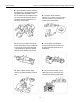
n Wrap the attached sealing pad 11 over the clamp and drain hose to insulate. (Refer to Fig. 12).
n Do not fold drain hose inside the indoor unit. (Refer to Fig. 13).
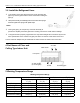
(2). Conrm that smooth drainage is achieved after the piping work.
Pour 20 oz. of water into the drain pan from the air outlet for conrming drainage.(Refer to Fig. 14).
Fig. 12
Air outlet
Fig. 13
Fig. 14
Fig. 10
Fig. 11
Watering can
Clamp
n
Drain Hose m
Tapering area
(Gray)
(When drain hose is connected)
Incline the drain hose
Not to be lifted
No folds or traps
Not to be
immersed in
water
Cramp
n
(Accessory)
.15 inch or less
Large seeing pad
(Accessory)
11