Installation & Operation Manual VFH-MB Series Inverter Multi Zone Ductless Mini-Split B-VFH09MB-1 B-VFH12MB-1 B-VFH18MB-1 B-VFH24MB-1 www.marsdelivers.
Installation & Operation Manual - VFH-MB 09/12/18/24 Series Table of Contents Part Ė : Technical Information .......................................................................4 1. Summary ......................................................................................................................4 6SHFL¿FDWLRQV ..........................................................................................................5 6SHFL¿FDWLRQ 6KHHW..................................................
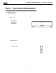
Installation & Operation Manual - VFH-MB 09/12/18/24 Series Part I : Technical Information 1.
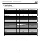
Installation & Operation Manual - VFH-MB 09/12/18/24 Series 6SHFL¿FDWLRQV 6SHFL¿FDWLRQ 6KHHW 0RGHO 3URGXFW &RGH % 9)+ 0% % 9)+ 0% &% 1 B/ &% 1 B/ 5DWHG 9ROWDJH 9 208/230 208/230 5DWHG )UHTXHQF\ +] 60 60 1 1 &RROLQJ &DSDFLW\ %WX K 9000 12000 +HDWLQJ &DSDFLW\ %WX K 9800 13000 $LU ÀRZ YROXPH 6+ + 0+ 0 0/ / 6/ &)0 430/394/359/312/271/241/224 430/394/359/312/271/241/224 3KDVHV 'HKXPLGLI\LQJ 9ROXPH / K )DQ 7\SH 0.8 1.
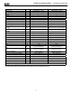
Installation & Operation Manual - VFH-MB 09/12/18/24 Series 0RGHO 3URGXFW &RGH 5DWHG 9ROWDJH 5DWHG )UHTXHQF\ 3KDVHV &RROLQJ &DSDFLW\ +HDWLQJ &DSDFLW\ $LU ÀRZ YROXPH 6+ + 0+ 0 0/ / 6/ %WX K %WX K &)0 'HKXPLGLI\LQJ 9ROXPH 3LQW K 9~ +] )DQ 7\SH 'LDPHWHU /HQJWK ';/ )DQ 0RWRU &RROLQJ 6SHHG 6+ + 0+ 0 0/ / 6/ )DQ 0RWRU +HDWLQJ 6SHHG 6+ + 0+ 0 0/ / 6/ 2XWSXW RI )DQ 0RWRU LQFK % 9)+ 0% % 9)+ 0% &% 1 B/ 208/230 60 1 a a 559/512/465/418/371/330/28
Installation & Operation Manual - VFH-MB 09/12/18/24 Series 2.
Installation & Operation Manual - VFH-MB 09/12/18/24 Series 3.
Installation & Operation Manual - VFH-MB 09/12/18/24 Series 4.
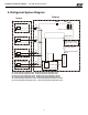
Installation & Operation Manual - VFH-MB 09/12/18/24 Series 5. Electrical Part 5.1 Wiring Diagram Ɣ,QVWUXFWLRQ 6\PERO 6\PERO &RORU 6\PERO 6\PERO &RORU 6\PERO 1DPH :+ :KLWH GN *UHHQ &$3 -XPSHU FDS YE
Installation & Operation Manual - VFH-MB 09/12/18/24 Series 5.
Installation & Operation Manual - VFH-MB 09/12/18/24 Series 6. Function and Control 6.
Installation & Operation Manual - VFH-MB 09/12/18/24 Series 2. FAN button 3UHVV WKLV EXWWRQ $XWR /RZ 0HGLXP ORZ 0HGLXP 0HGLXP KLJK +LJK VSHHG FDQ EH FLUFXODUO\ VHOHFWHG $IWHU SRZHUHG RQ $XWR IDQ VSHHG LV GHIDXOW 8QGHU '5< PRGH /RZ IDQ VSHHG RQO\ FDQ EH VHW XS ATUO Low fan Medium-low fan 1RWH 'U\ PRGH is Low fan speed only. Medium fan Medium-high fan High fan 3. MODE button 3UHVV WKLV EXWWRQ $XWR &RRO 'U\ )DQ +HDW PRGH FDQ EH VHOHFWHG FLUFXODUO\ $XWR PRGH LV GHIDXOW ZKLOH SRZHUed R
Installation & Operation Manual - VFH-MB 09/12/18/24 Series 10. TEMP button 3UHVV WKLV EXWWRQ \RX will VHH LQGRRU VHW WHPSHUDWXUH LQGRRU DPELHQW WHPSHUDWXUH RU RXWGRRU DPELHQW WHPSHUDWXUH RQ LQGRRU XQLW¶V GLVSOD\ 7KH VHWWLQJ RQ UHPRWH FRQWUROOHU LV VHOHFWHG FLUFXODUO\ DV EHORZ QR GLVSOD\ :KHQ VHOHFWLQJ " with remote controller or no display, temperature indicator on indoor unit displays set temperature; when selecting " ZLWK UHPRWH FRQWUROOHU WHPSHUDWXUH LQGLFDWRU RQ LQGRRU X
Installation & Operation Manual - VFH-MB 09/12/18/24 Series • 6OHHS –WKH VOHHS FXUYH VHWWLQJ XQGHU 6OHHS PRGH E\ ',< 1) Under Sleep 3 mode, press and hold "Turbo" button, remote control enters into sleep setting status, the time of remote control will display "1 hour", the temperature setting screen will display the corresponding temperature of last setting sleep curve and blink (The first entering will display according to the initial curve setting value from factory).
Installation & Operation Manual - VFH-MB 09/12/18/24 Series Operation Guide 1. General operation 1) $IWHU SRZHUHG RQ SUHVV 21 2)) EXWWRQ WKH XQLW ZLOO VWDUW WR UXQ 1RWH :KHQ LW LV SRZHUHG RQ WKH JXLGH ORXYHU RI PDLQ XQLW ZLOO FORVH DXWRPDWLFDOO\ 2) 3UHVV 02'( EXWWRQ VHOHFW GHVLUHG UXQQLQJ PRGH 3) 3UHVVLQJ RU EXWWRQ WR VHW WKH GHVLUHG WHPSHUDWXUH ,W LV XQQHFHVVDU\ WR VHW WKH WHPS DW $872 PRGH 4) 3UHVVLQJ )$1 EXWWRQ VHW IDQ VSHHG FDQ VHOHFW $872 )$1 /2: 0(',80 /2: 0(',80 0(',8 0 +,*+
Installation & Operation Manual - VFH-MB 09/12/18/24 Series 6.2 Brief Description of Modes and Functions Basic mode &RROLQJ 'U\LQJ +HDWLQJ $XWR )DQ 1. Cooling mode 1) Under cooling mode, fan and swing operate at setting status. Temperature setting range is 16~30°C (61°~86°F). 2) During malfunction of outdoor unit or when stopping operation due to fault protection, indoor unit keeps original operation status and the corresponding malfunction code will be displayed.
Installation & Operation Manual - VFH-MB 09/12/18/24 Series The small horizontal louver only operates under heating mode. Under other mode, the small horizontal louver always stays at the closed status; On the 9k/12k model, the small horizontal louver will start operation only when the big horizontal louver rotates to the second fixed angle (62°) under heating mode.
Installation & Operation Manual - VFH-MB 09/12/18/24 Series ,I WLPHU 21 DQG WLPHU 2)) DUH VHW DW WKH VDPH WLPH in 2)) VWDWXV WKH XQLW ZLOO remain OFF until reaching ON time. When reaching OFF time, the unit will be turned off automatically. The unit will repeat this pattern every 24 hours. If timer ON and timer OFF are the same, OFF command will prevail. 6. Memory function 1) 3RZHU RII PHPRU\ ZKHQ WXUQLQJ RQ WKH XQLW ƹ 0HPRU\ FRQWHQW 21 VWDWXV PRGH VZLQJ VWDWXV OLJKW VHW WHPSHUDWXUH VHW IDQ VSHHG J
Installation & Operation Manual - VFH-MB 09/12/18/24 Series 8°C (46°F) heating function is only valid under heating mode. After setting is accomplished, indoor unit displays 8°C (46°F).
Installation & Operation Manual - VFH-MB 09/12/18/24 Series Part ė : Installation and Maintenance 7. Notes for Installation and Maintenance Safety Precautions: Important! 9. If power cord or connection wire is broken, it must be be replaced by a qualified person. 10. A disconnect switch must be installed in the circuit. The disconnect switch should be all-pole parting and the contact parting distance should be more than 3mm. 11.
Installation & Operation Manual - VFH-MB 09/12/18/24 Series Safety Precautions for Installing and Relocating the Unit: To ensure safety, please be mindful of the following precautions. Warnings 1. When installing or relocating the unit, be sure to keep the refrigerant circuit free from air or substances other than the VSHFL¿HG UHIULJHUDQW $Q\ SUHVHQFH RI DLU RU RWKHU IRUHLJQ VXEVWDQFH LQ WKH UHIULJHUDQW FLUFXLW ZLOO FDXVH V\VWHP SUHVVXUH ULVH RU FRPSUHVVRU UXSWXUH UHVXOWLQJ LQ LQMXU\ or system failure
Installation & Operation Manual - VFH-MB 09/12/18/24 Series 8. Installation At least 6inch Space to the ceiling 8.
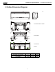
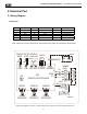
Installation & Operation Manual - VFH-MB 09/12/18/24 Series Installation procedures Start installation Preparation before installation Read the requirements for electric connection select installation location Select indoor unit installation location Prepare tools Select outdoor unit installation location Install the support of outdoor unit (select it according to the actual situation) Install wall-mounting frame, drill wall holes Connect pipes of indoor unit and drainage pipe Fix outdoor unit Inst
Installation & Operation Manual - VFH-MB 09/12/18/24 Series 8.2 Installation Parts-checking 1R 1 2 1DPH ,QGRRU XQLW 2XWGRRU XQLW 1R 8 9 3 &RQQHFWLRQ SLSH 10 4 'UDLQDJH SLSH :DOO PRXQWLQJ IUDPH &RQQHFWLQJ FDEOH SRZHU FRUG :DOO SLSH 11 5 6 7 12 13 0DNH VXUH WKH SRZHU VXSSO\ PDWFKHV ZLWK WKH UHTXLUHPHQW RI t h e DLU FRQGLWLRQHU 8QVWDEOH SRZHU VXSSO\ RU LQFRUUHFW ZLULQJ PD\ UHVXOW LQ HOHFWULF VKRFN ¿UH KD]DUG RU PDOIXQFWLRQ 3OHDVH LQVWDOO SURSHU SRZHU VXSSO\ FDEOHV EHIRUH
Installation & Operation Manual - VFH-MB 09/12/18/24 Series 3. Install Wall-mounting Frame &KRRVH WKH SRVLWLRQ RI SLSLQJ KROH DFFRUGLQJ WR WKH GLUHFWLRQ of RXWOHW SLSH 7KH SRVLWLRQ RI SLSLQJ KROH VKRXOG EH a OLWWOH ORZHU WKDQ WKH ZDOO PRXQWHG IUDPH $V VKRZn LQ )LJ Wall Space to the wall 150mm above Mark on the middle of it 5.
Installation & Operation Manual - VFH-MB 09/12/18/24 Series 7. Connect Wire of Indoor Unit 2SHQ WKH SDQHO UHPRYH WKH VFUHZ RQ WKH ZLULQJ FRYHU DQG WKHQ WDNH GRZQ WKH FRYHU $V VKRZn LQ )LJ Panel 8.
Installation & Operation Manual - VFH-MB 09/12/18/24 Series 8.6 Check after Installation and Test Operation 1. Check after Installation &KHFN DFFRUGLQJ WR WKH IROORZLQJ UHTXLUHPHQW DIWHU ILQLVKLQJ LQVWDOODWLRQ 1R 1 2 3 4 ,WHPV WR EH FKHFNHG +DV WKH XQLW EHHQ LQVWDOOHG secureO\" +DYH \RX performed a UHIULJHUDQW OHDNDJH WHVW" ,V KHDW LQVXODWLRQ RI SLSe refrigerant VXI¿FLHQW" ,V ZDWHU GUDLQing ZHOO" 3RVVLEOH PDOIXQFWLRQ 7KH XQLW PD\ GURS VKDNH RU HPLW QRLVH ,W PD\ FDXVH LQVXI¿FLHQW FRROLQJ
Installation & Operation Manual - VFH-MB 09/12/18/24 Series 9. Maintenance 9.1 Error Code 1. Requirement of malfunction display :KHQ VHYHUDO PDOIXQFWLRQV KDSSHQ DW WKH VDPH WLPH PDOIXQFWLRQ FRGHV ZLOO EH GLVSOD\HG FLUFXODUO\ 2. Malfunction display method +DUGZDUH PDOIXQFWLRQ LW ZLOO EH GLVSOD\HG LPPHGLDWHO\ SOHDVH UHIHU WR ³0DOIXQFWLRQ VWDWXV VKHHW´ 2SHUDWLRQ VWDWXV LW ZLOO EH GLVSOD\HG LPPHGLDWHO\ SOHDVH UHIHU WR ³0DOIXQFWLRQ VWDWXV VKHHW´ 2WKHU PDOIXQFWLRQ ,W ZLOO EH GLVSOD\HG DIWHU WK
Installation & Operation Manual - VFH-MB 09/12/18/24 Series 9LHZLQJ PDOIXQFWLRQ FRGH WKURXJK UHPRWH FRQWUROOHU &RPSUHVVRU RYHUORDG SURWHFWLRQ ZLWKLQ V GLVSOD\HG + GLUHFWO\ RQ QL[LHWXEH DIWHU V ,QGRRU XQLW DQG RXWGRRU XQLW GR QRW PDWFK +DUGZDUH PDOIXQFWLRQ /3 0DOIXQFWLRQ RI PHPRU\ FKLS +DUGZDUH PDOIXQFWLRQ EE 0DOIXQFWLRQ RI FRPSOHWH XQLWV FXUUHQW GHWHFWLRQ +DUGZDUH PDOIXQFWLRQ 8 0DOIXQFWLRQ SURWHFWLRQ RI RXWGRRU IDQ +DUGZDUH PDOIXQFWLRQ / 0RGH FRQÀLFW 2SHUDWLRQ VWDWXV E7 5HIULJ
Installation & Operation Manual - VFH-MB 09/12/18/24 Series 9.2 Procedure of Troubleshooting 1. Malfunction of Temperature Sensor F1, F2 Start Is the wiring terminal between temperature sensor and the controller loose or poorly connected? yes Insert the temperature sensor tightly no Malfunction is eliminated. no Is there short circuit due to loose parts? yes Secure the parts no Malfunction is eliminated.
Installation & Operation Manual - VFH-MB 09/12/18/24 Series 2.
Installation & Operation Manual - VFH-MB 09/12/18/24 Series 3.
Installation & Operation Manual - VFH-MB 09/12/18/24 Series 4.
Installation & Operation Manual - VFH-MB 09/12/18/24 Series All the indoor units show communication malfunction De-energize,check if the connection wire of indoor and outdoor unit and the wire of the eletric box is connected correctly Connected correctly? no Reconnect according to the wiring diagram yes Did this eliminate the malfunction? yes De-energize, check if the connection wire between the outdoor mainboard and the filter board according to the wiring diagram Connected correctly? Reconnect a
Installation & Operation Manual - VFH-MB 09/12/18/24 Series 10.
Installation & Operation Manual - VFH-MB 09/12/18/24 Series Replacement Parts Model B-VFH09MB-1 Location 1 2 3 4 5 6 7 8 9 10 11 12 13 14 15 16 17 18 19 20 21 22 23 24 25 26 27 28 29 30 31 32 33 34 35 36 Part Name Front Panel Display Board Filter Sub-Assembly Front Case Sub-Assembly Guide Louver Guide Louver (small) Crank Helicoid Tongue Sub-Assembly Left Axle Bushing Propeller Axle Bushing Evaporator Support Evaporator Assembly Cross Flow Fan Drainage Hose Fan Motor Wall Mounting Frame Motor Press Plate
Installation & Operation Manual - VFH-MB 09/12/18/24 Series Exploded View Model B-VFH12MB-1 38
Installation & Operation Manual - VFH-MB 09/12/18/24 Series Replacement Parts Model B-VFH12MB-1 Location 1 2 3 4 5 6 7 8 9 10 11 12 13 14 15 16 17 18 19 20 21 22 23 24 25 26 27 28 29 30 31 32 33 34 35 36 Part Name Front Panel Display Board Filter Sub-Assembly Front Case Sub-Assembly Guide Louver Guide Louver (Small) Crank Helicoid Tongue Sub-Assembly Left Axle Bushing Propeller Axle Bushing Evaporator Support Evaporator Assembly Cross Flow Fan Drainage Hose Fan Motor Wall Mounting Frame Motor Press Plate
Installation & Operation Manual - VFH-MB 09/12/18/24 Series Exploded View Model B-VFH18MB-1 40
Installation & Operation Manual - VFH-MB 09/12/18/24 Series Replacement Parts Model B-VFH18MB-1 Location 1 2 3 4 5 6 7 8 9 10 11 12 13 14 15 16 17 18 19 20 21 22 23 24 25 26 27 28 29 30 33 Part Name Front Panel Display Board Filter Sub-Assembly Screw Cover Front Case Guide Louver Guide Louver (Small) Helicoid Tongue Left Axle Bushing Stepping Motor O-Gasket of Cross Fan Bearing Ring of Bearing Cross Flow Fan Evaporator Support Evaporator Assembly Wall Mounting Frame Motor Press Plate Fan Motor Drainage Ho
Installation & Operation Manual - VFH-MB 09/12/18/24 Series Exploded View Model B-VFH24MB-1 42
Installation & Operation Manual - VFH-MB 09/12/18/24 Series Replacement Parts Model B-VFH24MB-1 Location 1 2 3 4 5 6 7 8 9 10 11 12 13 14 15 16 17 18 19 20 21 22 23 24 25 26 27 28 29 30 31 32 33 34 35 36 37 38 39 40 41 44 45 46 Part Name Front Panel Filter Sub-Assembly Screw Cover Front Case Sub-Assembly Guide Louver Small Guide Louver Swing Lever 2 Air Louver Left Axle Bushing Water Tray Assembly Rear Case Sub-Assembly Cross Flow Fan O-Gasket of Cross Fan Bearing Left Evaporator Support Evaporator Assemb
Installation & Operation Manual - VFH-MB 09/12/18/24 Series 11. Removal Procedure Caution: discharge the refrigerant completely before removal. Steps Procedure 1. Before disassembling the unit Before disassembling the unit. 2. Remove filter 1 2 Open the panel. Loosen the clasps on filter, push the filter inward and then pull it upward, then the filter can be removed. 3.Remove guide louver 1 Remove the axial bushing of big guidelouver.
Installation & Operation Manual - VFH-MB 09/12/18/24 Series Steps 2 Procedure Remove the rotating shaft of big guide louver from the groove, slightly bend thebig guide louver to remove it. big guide louver 3 Remove the axial bushing of small guide louver. axial bushing 4 Remove the rotating shaft of small guide louver from the groove, slightly bend the small guide louver to remove it. small guide louver 4.Remove panel 1 Loosen the clamps of the panel to remove the panel.
Installation & Operation Manual - VFH-MB 09/12/18/24 Series Steps 2 Procedure panel, to remove the display. 5.Remove front case 1 Remove the screws fixing electric box cover 2, to remove the electric box cover 2. electric box cover 2 screw clamp 2 Remove the screws fixing front panel, loosen the clamps, to remove the front case.
Installation & Operation Manual - VFH-MB 09/12/18/24 Series Steps Procedure 6.Remove swing fan blade 1 Loosen the clamps fixing swing connecting rod, to remove the swing connecting rod. clamp 2 swing connecting rod clamp remove the swing fan blade. swing fan blade 7.Remove electric box sub-assy heat exchanger thermistor 1 Remove the indoor tube temp. sensor. grounding wire 2 Remove the screws fixing grounding wire, to remove the grounding wire.
Installation & Operation Manual - VFH-MB 09/12/18/24 Series Steps 3 Procedure to remove the cover. electric box cover electric box cover sub-assy screw 4 Remove every wiring terminals, and remove the electric box cover sub-assy. 7.Remove evaporator sub-assy pipe clamp auxiliary piping 1 Remove the screws fixing connection pipe clamp, to remove the connection pipe clamp.
Installation & Operation Manual - VFH-MB 09/12/18/24 Series Steps Procedure auxiliary piping 2 Remove the screws fixing evaporator sub-assy, slightly regulate the tube, to remove the evaporator sub-assy. evaporator sub-assy 8.Remove cross fan blade and motor 1 motor, to remove the motor. up&down swing motor 2 to remove the motor.
Installation & Operation Manual - VFH-MB 09/12/18/24 Series Steps 3 Procedure Remove the screws fixing motor clamp, to remove the motor clamp. screw 4 Remove the cross fan blade and motor. bearing cushion rubber base 5 6 Remove the shafting bearing cushion rubber base cross fan blade blade and motor, and then remove the motor.
Installation & Operation Manual - VFH-MB 09/12/18/24 Series Appendix: Appendix 1: Reference Sheet of Celsius and Fahrenheit Conversion formula for Fahrenheit degree and Celsius degree: Tf=Tcx1.8+32 Set temperature )DKUHQKHLW )DKUHQKHLW GLVSOD\ &HOVLXV˄ć˅ WHPSHUDWXUH ˄̧˅ ˄̧˅ 61 60.8 16 62/63 62.6 17 64/65 64.4 18 66/67 66.2 19 68 68 20 )DKUHQKHLW )DKUHQKHLW GLVSOD\ &HOVLXV˄ć˅ WHPSHUDWXUH ˄̧˅ ˄̧˅ 69/70 69.8 21 71/72 71.6 22 73/74 73.4 23 723/326 75.2 24 77 77 25 )DKUHQKHLW )DKUHQKHLW GLVSOD\ &HOVL
Installation & Operation Manual - VFH-MB 09/12/18/24 Series Appendix 3: Pipe Expanding Method Pipe Note: Pipe cutter Improper pipe flaring is the main cause of refrigerant leakage.
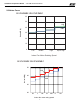
Installation & Operation Manual - VFH-MB 09/12/18/24 Series Appendix 4: List of Resistance for Temperature Sensor Resistance Table of Ambient Temperature Sensor for Indoor and Outdoor Units(15K) 7HPS R) 1.4 3.2 5 6.8 8.6 10.4 12.2 14 15.8 17.6 19.4 21.2 23 24.8 26.6 28.4 30.2 32 33.8 35.6 37.4 39.2 41 42.8 44.6 46.4 48.2 50 51.8 53.6 55.4 57.2 59 60.8 62.6 64.4 66.2 5HVLVWDQFH Nȍ 138.1 128.6 121.6 115 108.7 102.9 97.4 92.22 87.35 82.75 78.43 74.35 70.5 66.88 63.46 60.23 57.18 54.31 51.59 49.
Installation & Operation Manual - VFH-MB 09/12/18/24 Series Resistance Table of Ambient Temperature Sensor for Indoor and Outdoor Units(20K) 7HPS R) 5HVLVWDQFH Nȍ 7HPS R) 5HVLVWDQFH Nȍ 7HPS R) 5HVLVWDQFH Nȍ 7HPS R) 5HVLVWDQFH Nȍ 1.4 3.2 5 6.8 8.6 10.4 12.2 14 15.8 17.6 19.4 21.2 23 24.8 26.6 28.4 30.2 32 33.8 35.6 37.4 39.2 41 42.8 44.6 46.4 48.2 50 51.8 53.6 55.4 57.2 59 60.8 62.6 64.4 66.2 181.4 171.4 162.1 153.3 145 137.2 129.9 123 116.5 110.3 104.6 99.13 94 89.17 84.61 80.31 76.
Installation & Operation Manual - VFH-MB 09/12/18/24 Series Resistance Table of Ambient Temperature Sensor for Indoor and Outdoor Units(50K) 7HPS R) 1.4 3.2 5 6.8 8.6 10.4 12.2 14 15.8 17.6 19.4 21.2 23 24.8 26.6 28.4 30.2 32 33.8 35.6 37.4 39.2 41 42.8 44.6 46.4 48.2 5HVLVWDQFH Nȍ 853.5 799.8 750 703.8 660.8 620.8 580.6 548.9 516.6 486.5 458.3 432 407.4 384.5 362.9 342.8 323.9 306.2 289.6 274 259.3 245.6 232.6 220.5 209 198.3 199.1 178.5 169.
'XH WR RQJRLQJ SURGXFW LPSURYHPHQWV VSHFLILFDWLRQV DQG GLPHQVLRQV DUH VXEMHFW WR FKDQJH DQG FRUUHFWLRQ ZLWKRXW QRWLFH RU LQFXUULQJ REOLJDWLRQV 'HWHUPLQLQJ WKH DSSOLFDWLRQ DQG VXLWDELOLW\ IRU XVH RI DQ\ SURGXFW LV WKH UHVSRQVLELOLW\ RI WKH LQVWDOOHU $GGLWLRQDOO\ WKH LQVWDOOHU LV UHVSRQVLEOH IRU YHULI\LQJ GLPHQVLRQDO GDWD RQ WKH DFWXDO SURGXFW SULRU WR EHJLQQLQJ DQ\ LQVWDOODWLRQ SUHSDUDWLRQV ,QFHQWLYH DQG UHEDWH SURJUDPV KDYH SUHFLVH UHTXLUHPHQWV DV WR SURGXFW SHUIRUPDQFH DQG FHUWLILFDWLRQ $OO SUR