Electric Winch Limited One (1) Year Warranty Statement Comeup Industries Inc. ( ) warrants to the original purchaser that the mechanical compnents and electrical components of the Electric Winch will be free of defects in material and workmanship for one (1) year. All mounting kits and other accessories carry one (1) year limited warranty against defects in material workmanship. This Warranty applies only to the original purchaser of the winch.
Electric Winch Thank you for purchasing a Winch. This manual covers operation and maintenance of the winch. All information in this publication is based on the latest production information available at the time of printing. General Safety Precautions The winch has been designed to give safe and dependable service if operated according to the instructions. Please read and understand this manual before installation and operation of the winch.
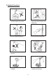
I . Installation Precaution General Safety Precaution ! DANGER The following environmental conditions may result in the possible causes of hoist trouble.
II.
III. Winching Principles Percentage Duty Cycle WARNING ! Never hoist over the rated percentage duty cycle. The life of the winch is depending on the conditions of the load and working frequency. In the long time operation, make sure to use the machine within its continuous ratings. Continuous ratings means the percentage duty cycle (%ED) is subject to the rated voltage, rated frequency and a 63% of rated load.
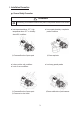
Calculating Fleet Angle ● The winch should be mounted as close to centre and as perpendicular as possible to the direction of the line pull. This will keep the wire rope fleet angle centre on the drum as small as possible. ● If the proper fleet angle is not maintained, the wire rope could wind onto one side of the drum. Correct Distance θ θ Drum Length Fleet Angle Experience has shown that the best wire rope service is obtained if the maximum fleet angle is not more than 1.
IV. Compliance with EU Directives Electric Winches shall comply with the following regulations 1. European Standards of EN 14492-1 for Power Driven Winches came to effect from 29th. December 2009 2. European Machinery Directive 2006/42/EC. 3. European Directive on Electromagnetic Compatibility ( EMC ) 2004/108/EC 4. European Low Voltage Directive ( LVD ) 2006/95/EC Extracts from the Directives 1. EN 14492-1 Section 5.15.6 Wire Rope Wire rope minimum break to be twice winch rating 2. EN 14492-1 Section 5.7.
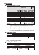
V. Working Method Power Lead and Switch Cord Sections Remote Control Power Lead Winch Model Direct Control W/Switch CPB-213 1.5 mm2 CP-200/250/300 CP-500 CP-500T CP-750T CP-900T CWG-10077 CWG-30075 CWG-10151 CWG-30151 CWG-30375/30565/ 30750/31500 5.5 mm2 CWG-34000 8.0 mm2 3.5 mm2 3.5 mm2 3.5 mm2 3.5 mm2 3.5 mm2 3.5 mm2 5.5 mm2 3.5 mm2 1.25 mm2 3.5 mm2 3.5 mm2 W/Switch PB-331 1.25 mm2 3.5 mm2 3.5 mm2 3.5 mm2 3.5 mm2 2 1.25 mm 1.25 mm2 3.5 mm2 3.5 mm2 2.0 mm2 2.
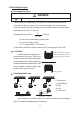
Grounding To prevent the risk of electric shock, the power plug must be plugged into a matching outlet and grounded in good condition. Up and Down Switching To lift a load, press ↑ button and drum will rotate as shown below operation. To lower a load, press ↓ button and drum will rotate as shown below. To stop winching, release ↑or ↓ button. To have an emergency stop function, press the emergency stop button (option). Rotate the button clockwise for returning.
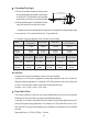
Wire Rope Selections Lifting Capacity at 50Hz kg Dia. mm CP-200 200 6 Winch Model Recommended Wire Rope Minimum Length Const. Breaking (m) Strength kg 30 6 x 19 2,010 Safety Factor at 50Hz 10 CP-250 250 6 30 6 x 19 2,010 8 CP-300 300 6 30 6 x 19 2,010 6.7 CP-500/500T 500 7 60 6 x 19 2,700 5.4 CP-750T 750 9 60 6 x 24 3,750 5 CP-900T 900 10 30 6 x 24 4,640 5.1 CWG-10077 300 6 60 6 x 19 2,010 6.7 CWG-10151 400 9 60 6 x 24 3,750 9.
Brake Replacement and Adjustment ● For CP-200/250/300/500/500T, CWG-30075 winches There is no brake adjustment function. Once the brake disc is considerable worn, replace it with new one. Condition: Brake distance is more than 1.5% of rope length to be wound-in during 1 min or the brake disc thickness is smaller than 8.
Brake Specification CP-200 Coil Volt. V 110 Brake Disc Diameter mm x q’ty 95 x 1 103 Brake Gap mm 0.3 CP-250 110 95 x 2 103 0.45 CP-300 CP-500 220 95 x 2 103 0.45 220 95 x 2 228 0.45 CP-500T 220 95 x 2 228 0.45 CP-750T 380 150 x 1 84, 36, 48 0.45 CP-900T 380 150 x 1 84, 36, 48 0.45 CWG-10077 110 95 x 2 64 0.45 CWG-10151 DC 220 140 x 1 436 0.35 CWG-30075 220 95 x 2 434 0.45 CWG-30151 DC 220 140 x 1 436 0.
VI. Cart Puller Capacity Choose the Right Winch In most pulling applications you are dealing with a rolling road rather than pulling a dead weight. Resistance to rolling is mostly influenced by the load, rolling resistance, track gradient, track curvature, track conditions. ● Load: Calculate the total weight of the loaded cart to be moved simultaneously. ● Rolling resistance: Resistance to rolling is influenced by the wheel journals, type of lubrication used and the ambient temperature.
Horizontal Load Reversing The horizontal load reversing allows 2 pieces of wire rope to be spooled onto the first layer of grooved drum. As one rope winds onto the drum and the other rope winds off an equal amount. It is important to know how each of the wire rope will be coming off of the drum, that allows the correct grooving to be provided. VII.
CP-500T Winch Standard Version Switch with an emergency stop button Red Black Red Black Brown Gray Quick Connector Red Black Red Black Brown Emergency Stop Brown Blue Gray Blue Brown Blue Gray Blue Gray R S T Quick Connector Up R S T Up Down Down Pendant Switch CPB-213 Motor 380V U1 V1 U2 V2 Pendant Switch PB-331 Motor 380V U1 V1 U2 V2 Red Red Black Brown Black Brown Blue Gray Blue Gray Red Black Brown Emergency Stop Red Black Brown Blue Gray Blue Gray Quick Connector
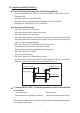
CP-500 Winch Standard Version Red Black Brown Red Black Brown Gray Blue Gray Blue Switch with an emergency stop button Emergency Stop Red Black Brown Red Black Brown Blue Gray Quick Connector Blue Gray Quick Connector R R T Up T Up Down Down Brake Brake Pendant Switch PB-331 Pendant Switch CPB-213 Motor 220/230/240V Motor 220/230/240V Low voltage control assembly and Switch with an emergency stop button Red Black Brown Blue Gray Brake Red Black Brown Blue Gray LV-320 Pendant S
CWG-30075 Winch Standard Version Brown Blue Blue Brown Brake Gray Black Black Black Red Red Black White White Grounding Up Brake Gray Grounding Up S R T S R T Power Supply Power Supply Down Down Motor Pendant Switch CPB-213 200~220V Blue Brown Motor Pendant Switch CPB-213 380V Brake Black Red Grounding Up S R T Power Supply Down 400~415V Motor Pendant Switch CPB-213 Low voltage control assembly and Switch with an emergency stop button Switch with an emergency stop butto
CWG-30151 Winch Standard Version Blue Brown Brake Blue Brown Gray Black Black Black Red Red Black White White Grounding Up Brake Grounding Up S R T S R T Power Supply Power Supply Down Down Motor Pendant Switch CPB-213 380V 415V Motor Pendant Switch CPB-213 Switch with an emergency stop button Blue Brown Gray Black Blue Brown Brake Black Black Red Red White Emergency Stop Up Brake Black White Emergency Stop Grounding S R T Grounding Up S R T Power Supply Power Supp
VIII. Checking and Trouble Shooting Checking Reference Remark:1. The specified person performs the checking of winch. 2. Divide the checking into daily checking and periodic checking. 3. The checking items and checking method in daily and periodic checking shall be carried out and different according to the using frequency.
Trouble Shootings Checking the winch for smooth operation by pressing ↑ or ↓ button of pendant switch. When winch fails to start after several attempts, or if any defective operation to be happened, check followings.
COMEUP INDUSTRIES INC. No.112, Nanyang St., Xizhi Dist., New Taipei City, Taiwan 22152 Tel: +886-2-2694-7011 / Fax: +886-2-2694-7053 Email: info@comeup.com.tw http://www.comeupwinch.