
Specifications


Table Of Contents
Enter Base Level: Press
ITCM,
then
dial
m
# 7 4 6
*.
Non-Square System: Each
programmable button at every station
can be assigned individually (mapped)
to select any line assigned to that
station or to provide other button
functions. Programmable buttons can
be assigned as direct station select
(DSS) buttons to provide one-key
access to system stations.
Programmable buttons can be
assigned as idle (blanked) to provide
wtodial
buttons for the user.
NOTE: When a line is reassigned from
9
defaulted button location to a
Different
button location, the defaulted
5utton
must then be assigned to an
‘die
condition (blanked). This action
must be taken to ensure that status
hdications for the line will appear at
!he LED of the button that is now
assigned to have
tine
appearance.
4 button must be blanked even though
‘t
does not appear on the particular
telephone being programmed.
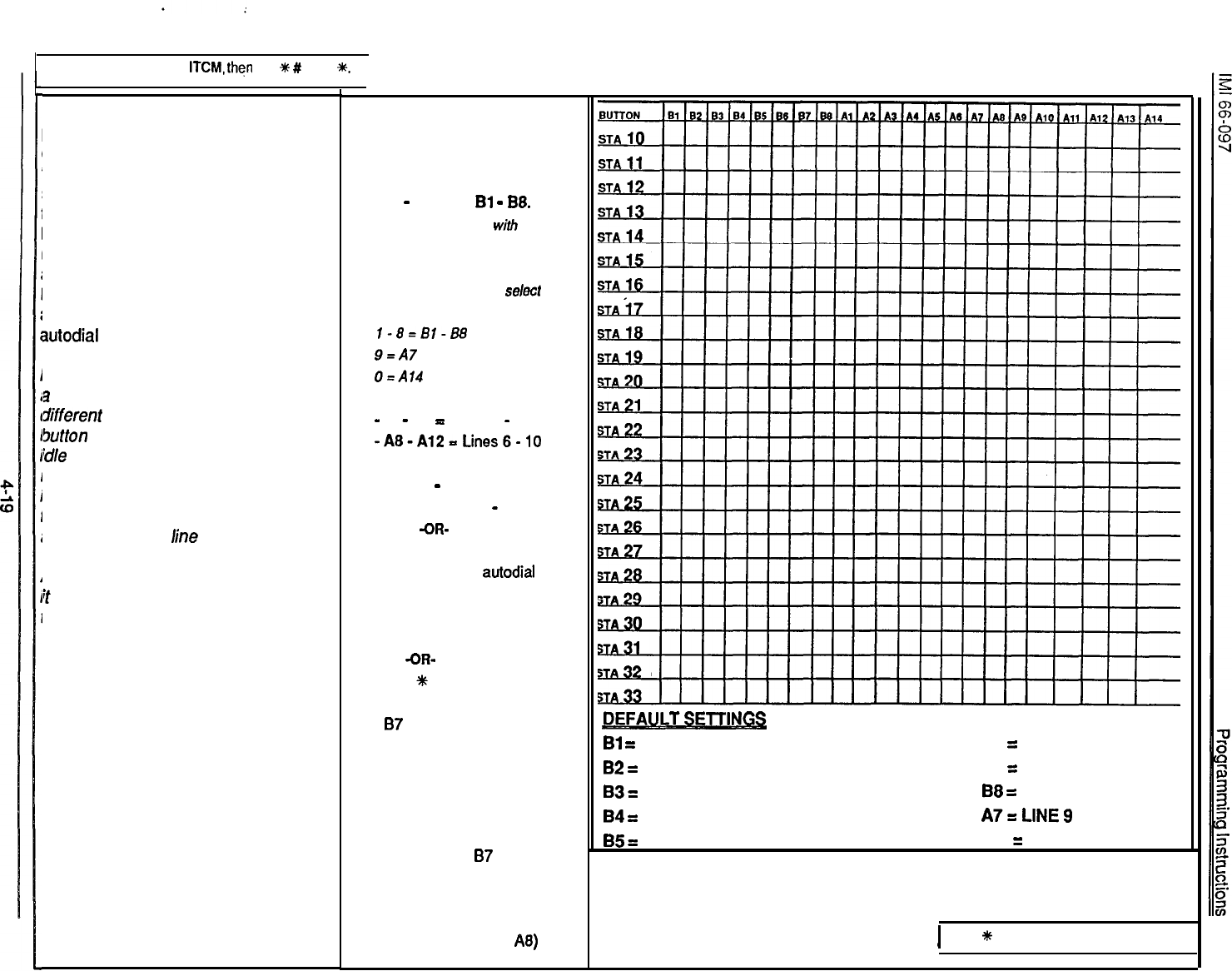
1. Dial 59.
2. Dial port ID (1 O-33)
3.
Press station button to be
programmed.
l Al
-
Al4 and
Bl
-
B8.
NOTE: If programming
with
a model
6702X or 6714X telephone that does
not include a full complement of
buttons, dial a number to select the
button to be programmed
l-8=Bl-B8
9=A7
O=A14
4. Press prog. button to assign line
-
Al
-
A5
=
Lines 1
-
5.
-A8-A12=Lines6-10
-OR-
- Dial 10
-
33
for DSS Sta 10
-
33
-OR-
Press TAP for
idle
(blank)
buttons for user
autodial
purposes
5.
Press # + PORT ID for
next station
-OR-
Press
t
for next feature.
EXAMPLE: To re-assign line 7
from
87
default to A8 location
at station port 15 containing
model 6706X telephone,
1. Dial 15 (for station port 15)
2. Press A8 (to select button A8)
3. Press A9 (to re-assign line 7)
4. Dial 7 (to select
87
location
even though not present on
model 6706X telephone).
5. Press TAP (to move line 7
status LED for button A8)
DEFAULTSETLI_NILS
Bi
=
LINE 1
B6
=
LINE 6
82
=
LINE 2
B7
=
LINE 7
83
=
LINE
3
88
=
LINE 8
84
=
LINE 4
A7sLlNE9
85
=
LINE
5
Al4
=
LINE 10
I
Press
*
SPKR to end programming.