
Specifications


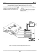
Table Of Contents
IMI
66-097
Installation
Connecting A Power Failure Telephone
The system provides a tip and ring pair connected to
line one that is to be used as an emergency power
failure circuit. This power failure pair is located on
Mod jack 1 for all common equipment models. This
jack is the right-most jack when facing the right side of
the cabinet. The power failure pair is only active
during an AC power failure. An industry standard
single-line telephone, such as a Comdial2500-xx can
be connected
to
the power failure pair and used to
provide communications capability should the AC
power to the system be interrupted.
TYPICAL COMMON
EQUIPMENT
CABiNET
11024
SHOWN1
TYPICAL
INUJSTRY
STANDARD NON-ELECTRIC
TELEPHONE
(POWER FAILURE
INTERFACE1
Figure 3-6. Connecting A Power
Failure
Station
ConnectIon.
3-13