
Specifications


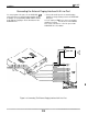
Table Of Contents
Installation
IMI
66-097
Connecting Telephones To The System
Connecting Multiline Telephones
Place individual telephones as desired and in keeping
with accepted industry and office standards. Mount
the telephones on the wall or on a desk as needed.
The telephone housings are desk/wall reversible for
this purpose.
Connections between the common equipment and
the stations for both the NO820 and the N1024 are
via two type
66M-xx
connector blocks that are cable
connected to the common equipment
50-pin
male
connectors. Table 3-2 shows the station
connection details.
The maximum distance allowed from the common
equipment to the station when using
#24
gauge,
twisted-pair cable is 1500 feet.
NOTE: If spare conductors exist in the cables that are
run between the common equipment
66M-xx
connector blocks and the station jacks, it is a
good practice to connect them to earth ground.
Doing this may help prevent them from
inducing radio frequency
and/or
AC
interference into the system.
The polarity between the individual wires
in a particular voice or data pair is
not
critical; however, do not connect the voice
circuits to the data circuits.
Pairing The Stations
Station ports are paired for both data and overload
protection as follows:
lo--11
14--15
18--19
22--23
26--27
30--31
12--13 16--17
20--21
24--25
28--29 32--33
Connecting Single-Line Proprietary
Telephones
You can connect a single-line proprietary telephone
(product code 6701X-xx) telephone at any port except
station port 10. You must program the station port to
be compatible to this type of telephone using
instructions provided in Chapter 4.
Placement and distance limits for the single-line
proprietary telephone are the same as those specified
for the multiline telephones.
Connecting Industry-Standard Telephones
You can connect an industry-standard telephone
(IST),
such as the
Comdial2500,
to the voice pair of
station ports 26 and 28. When you do this, you must
program these ports to be compatible with this type of
telephone (program the ports as OPX ports). Refer to
Chapter 4 for programming details.
When you connect an IST to station ports 26 and 28,
there are several percautions that you must take.
They are as follows:
Connect the IST to the tip and ring pair of the station
port. Do not connect any wiring to station port’s data
pair.
The battery-feed voltage is 24 VDC at a constant
current of 42 ma. In distance, this translates to a
maximum location distance of 2000 feet for an IST
with 300 ohms of impedance including the #24
twisted-pair station wiring.
The XE system’s
55-volt
ring generator supports a
telephone with a ringer equivalence number (REN) of
2.0.
The
IST
must be installed as an on-premise
device because the IST station ports
provide neither the long-loop capacity nor
the lightning protection that an off-premise
telephone requires.
Connecting
T;zN&tiinal
DSS/BLF
The optional
DSS/BLF
consoles may be installed at
any station port except port 10 to work in conjunction
with a companion station connected to the adjacent
port (for example,
poti
10 for station and port
11
for
console).
The model
EB32X-xx,
DB32-xx,
DB32Sxx,
DB40-xx,
and
DB70-xx
DSS/BLF consoles are all compatible
with the XE system. The station
potl
to which they are
connected must be programmed as a DSS/BLF
console port. The console buttons are fixed for
DSS/BLF
operation beginning with station 10 and
ending with the maximum station number in the
system. These buttons also provide autodiai locations
at a second level of storage (accessed with the HOLD
button function). Additionally, any buttons, from
beyond system station capacity through a maximum of
32, are available as
autodial
locations at the first level
of storage. For example, a model
N1024
key system
and a
EB32X-xx
or
DB32-xx
console will fix the first 24
console buttons as DSS/BLF buttons, and provide the
remaining eight buttons as
autodial
buttons. Plus, it
will provide
autodial
locations at the second level of
storage for the first 24 buttons. It provides a total of 32
autodial
storage location. For larger consoles, any
buttons beyond a maximum of 32 will still be blanked.
3-8