COMDIAL Executech II • Installation • Maintenance • Programming
1311 66-Q31 July, 1986 -I c; INSTALLATION AND MAINTENANCE INFORMATION FOR THE MODEL 616 ELECTRONtC KEY SYSTEM SERIAL NUMBER YvvwvvYwwwvvvvvvvYvwv . . . 111 - . . .’ _ -_-_c /-_--_ ‘. _.
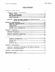
. Table IMI 66-031 Of Contents ;‘ L TABLE OF CONTENTS CHAPTER 1 INTRODUCTION . . ..*.................................. SECTION 1 GENERAL INFORMATION ............................. MANUAL SCOPE ........................................... GENERAL DESCRIPTION .................................... KEY SYSTEM FEATURES .................................... SPECIFICATIONS ........................................ SECTION 1 1 : 2 INSTALLER/USER RULES INFORMATION REGARDING FCC AND REGULATIONS . . . . . . .
. IMI 66-031 Introduction CHAPTER 1 INTRODUCTION SECTION 1 GENERAL INFORMATION MANUAL SCOPE This publication contains installation and maintenance information for the Model 816 electronic key system and associated electronic key telephone sets. The installation procedures detailed in this manual, for the most part, should be performed by a trained technician. The following service items may, however, be performed by any user at his or her discretion.
I Introduction IMI 66-031 : L The KSU is a fully electronic key service unit. It is essentially a special purpose computer system acting as a communications controller between TELCO or PABX supplied lines and propriatery 3-line and 8-line telephone stations. The KSU is contained in a functional, modern-style metal housing of contemporary design in keeping with the needs-of the modern offlce enviroment. .It is engineered to be wall or rack mounted.
Introduction c IMI 66-031 system defaults to system-wide, all-call paging in zone D with all stations having both receive and originate capability. A station port can be programmed to interface with an external paging amplifier. It can be dial accessed from the other stations in the system. A line port can also be programmed to interface with an external paging amplifier. This paging amplifier can be accessed from the stations in the system with the line select key.
f w Introduction IMI 66-031 '; f , L The user must lift the handset to complete the call voice link. Lifting the handset or pressing any other key will cancel further automatic redial action. Users of the optional speakerphone station can complete the call voice link by pressing the MONITOR OFF key instead of lifting the handset. X_/ The system will detect an A-lead contact closure on certain incoming lines.
Introduction IMI 66-031 The internal speaker at each station provides call-announce capability over the intercom link. A handsfree response to a call-announce call can be made. This response is transmitted by the microphone built into the handset. Call transfer allows incoming calls to be transferred from one station to another, via the intercom link, in one of two ways. If both stations have access to the incoming line, a common line pickup transfer can be effected.
Introduction IMI 66-031 W.nsQ~&L~~ _ ._ The system attendant station (station 10) can be called whenever the 0 key is dialed on the intercom line. The ringing pattern of an incoming call follows the ringing pattern of fhe TELCO or PBX system. The ringing pattern of a tone signalled intercom call presents two tone bursts sounded every 4 seconds. A voice signalled intercom sounds two tone bursts one time. Any station can be set to a do-not-disturb mode with the MONITOR. key.
. Introduction IMI-66-031 d lgSSLvuithanskseLw Each station comes equipped with a built-in direct station select intercom for stations 12 through 25. Access to these stations is effected by pressing the intercom select key and then pressing one of the memory keys. This action completes a voice announced intercom call to the selected station. Any active outside line is automatically placed on hold when the intercom select key is pressed. When custom calling features are available via a .
Introduction IMI 66-031 ’ L Should the intercom line be selected with no subsequent action taking place, the system will timeout the active status and return the station to an idle state. Bach station is equipped with a last number redial feature. This feature will save the last number manually dialed from the keypad. It will redial the saved number upon key command. A newly dialed number will automatically replace a currently saved number.
IMI 66-031 mbsf(eus,SneedDialL 1 .- ‘ _ mixture of 3-line and 8-line telephone can be standard, handsfree stations or full ‘. ghen it is actuated. Th is Itions with a programmed lrammable.memory dialing features available These memory keys can be programmed to .c dialing purposes. The stored numbers can lth and can include line or intercom ', pauses, and flash signals. A pause is key is pressed, and a flash signal is stored .s pressed.
L Introduction IMI 66-031 s b The system can be programmed on a per station basis to enable ringing line preference. When ringing line preference is enabled at a station, taking it off-hook will automatically connect it to an outside line which has audible ringing. A line select key will not have to be pressed. This feature enables a key action to save the last number manual1 dialed from the keypad. The same key action will redial the save8 number when it is pressed at a later time.
Introduction IMI 66-031 , System toll call restriction can be configured, by Class Of Service programming, to prohibit some or all stations from calling a wide range of number combinations. The restricted numbers are specified on programmable restricted number tables which are assigned on a per station and per line basis. In general, toll restriction works as follows: The programmable tables of restricted numbers contain entries of up to 16 digits each.
_ IMI 66-031 Introduction , c Table 1.
.._ Introduction IMI 66-031 & SECTION 2 INSTALLER/USER INFORMATION REGARDING FCC RULES AND REGULATIONS This electronic key system complies with Federal Communications Commission (FCC) Rules, Part 68. The FCC registration label on the KSU contains the FCC registration number, the ringer equivalence number, the model number, and the serial number or production date of the system.
_ IMI 66-031 Introduction ; . PARTY LINES AND COIN LINES Local telephone company regulations may not permit connections to party lines and coin lines by anyone except the telephone operating company. TROUBLESHOOTING If a service problem occurs, first try to determine if the trouble is in the on-site system or in the telephone company equipment. Disconnect all equipment not owned by the telephone company.
IMI 66-031 Introduction r. If necessary, the user should consult the manufacturer or an experienced radio/television technician for additional Suggestions. The user may find the following booklet prepared by the Federal Communications Commission helpful: "HOW to Identify and Resolve Radio-TV Interference Problems." This booklet is available from the Government Printing Office, Washington D.C. 20402. Stock No. 004-000-00345-4. RINGER EQUIVALENCE NUMBER The REN of each line of the KSU is 0.3s.
Installation IMI 66-031 * CHAPTER 2 INSTALLATION .,f MOUNTING 0 CONSIDERATIONS The KSU cabinet should be attached vertically to any sturdy, flat, surface. It may be vertically rack mounted if desired. It must be located within 6 feet of a properly grounded, three-wire, 117VAC, electrical outlet. The distance between the KSU and the TELCO/PBX jacks must be 25 feet or less as per FCC requirements. A nominal distance of 7 feet is recommended.
. IMI 66-031 Installation ; _ 19.25 INCHES hNElEr----i o-al I Figure 1. KSU Mounting Dimensions W&&Wi%&&&Qtina Place the individual telephone stations as desired and in keeping with accepted industry and office standards. A station can be wall mounted if necessary. Use a wall mounting bracket (part number 701032-056) for this purpose. CABLE ROUTING Cable may be routed concealed or visible as the installation location requires.
s IMI Installation 66-031 ’ L f- c CONNECTIONS Connection between the KSU and the TELCO or PABX line is via four-wire cable and modular plug/jack connection. The maximum length of a line cable is determined by the limitations detailed above. A-Lead Control The KSU inputs of TELCO lines 7 and 8 are configured to detect an A-lead (A and Al) control signal when it is applied at the modular line jack of the KSU.
_ Installation IMI 66-031 The polarity between the individual wires in a particular voice or data pair is not critical; however, do not connect the voice circuits to the data circuits: To do SOI will make a station inoperative as well as the adjacent odd or even station. 3. After making the wiring connections discussed above and illustrated in Figures 2 through 5, double check all connections and cable routing to insure accuracy.
_-__ __-.__-_-~___ Installation IMI 66-031 I To apply AC power to the KSU, connect the AC power cord to a properly grounded, three-wire, 117VAC electrical outlet. A plug-in, power line surge protector should be installed between the KSU power cord and the AC outlet. Do not connect the AC power cord until the installation has been checked per the instructions given later .in this chapter. It is recommended that a grounding wire, separate from the three wire AC line cord, be used.
i. Installation 4 2 ; %?Etews IMI 66-031 .+ can be programmed to be a PA station port e!+w IaLii e ephone station port (see Chapter 4 for programming details). When this is done, the audio input of a PA amplifier can be connected to the audio pair of the station port as illustrated in Figure 3. The connection must be isolated with a 600 ohm to 600 ohm audio matching transformer. Terminate the audio input of the PA amplifier with a 620 ohm (nominal value) resistor.
Installation IMI 66-031 An optional station is available which is equipped with a 14 station Busy Lamp Field (BLF). up to eight BLF stations can be connected to the system. A BLF station can be connected to any odd or even station port in the system per the following guidelines. l The installed distance between the KSU and the BLF station must be limited to 1000 feet or less. OThe data-line paired station port cannot be used as a BLF station connection or as a regular station connection.
I IMI 66-031 Installation CLIP TERM l----1 24V@ 0.4A MAX VOLTAGE CLAMPING DIODE RECOMMENDED CONTACT CLOSURE External Signalling --Typical Connection Figure 2. 600-h TO KSU STATION TO 6OOA (1:l) PA SYSTEM AUDIO TRANSFOF 111 r PORT 23 OR 25 IF ENABLE IS REQUIRED OR TO ANY UNUSED STATION PORT IF ENABLE IS NOT REQUIRED. I AUDIO INPUT : . . ENABLE INPUT t TO KSU EXTERNAL CONTROL CONNECTION POINTS ON 66M-XX CONNECTOR BLOCK.
Installation
IMI Figure 4.
Installation IMI GREEN-WHITE 1 J 1 3 1 12 13 I RED-SLATE SLATE-RED E 1 1 l4 -_c._.. . I ~~ 111 1 z -I BLACK-BROWN BROWN-BLACK YELLOW-BLUE BLUE-YELLOW YELLOW-ORANGE ORANGE-YELLOW/ YELLOW-GREEN GREEN-YELLOW YELLOW-BROWN BROWN-YELLOW YELLOW-SLATE SLATE-YELLOW VIOLET-BLUE 15 41 I6 ,~ ” .
Installation IMI 66-031 .. CHECKOUT The system operating features are set to the system default conditions at initial power up. These conditions provide a basic operating system. They can be altered as described in the Chapter 4 Class Of Service programming discussion; however, the system should be initially checked out with the default conditions in place. The system default conditions are as follows. -All lines are DTMF -Voice signalling attempted first when intercom call is made -1 sec.
. Installation IMI 66-031 VOICE PAIR: 45 OHMS TYPICAL (40 OHMS MIN.--150 OHMS MAX.) DATA PAIR: 45 OHMS TYPICAL (40 OHMS MIN.--150 OHMS MAX.) , .? Readings which are outside of the above range indicate a possible wiring or station problem. 2. Connect the 250pair cables, and plug the AC power plug of the KSU into the electrical outlet. 3. Measure the voltage across one voice line and one data line and then across the other voice line and the other data line for each even and odd station.
Installation SYSTEM IMI 66-031 CLOCK INFORMATION 2 sisidaaaa From station 10, set the system clock to the current time.as follows: 0ITCM 1. Press 2. Dial the clock date with the key pad keys 00 YEAR , then dial 00 MONTH 00DAY 0000 HOUR MINUTE NOTE Values less than 10 must be dialed as OX, and hours must be expressed in the 240hour format. 3. If the SMDR printer is installed and operating, the clock date will be printed as illustrated in the following typical example.
IMI 66-031 Installation , The system clock will continue to run for at least 30 minutes after AC power has been removed form the system. If power is restored within the 30-minute backup period, the following printing sequence will occur: OFF TIME ** MO/DY/YR HR:MN (time of power outage) ** MO/DY/YR HR:MN (time of power return) If power is not restored within the backup period, the following printing sequence will occur when the power is restored.
IMI Operation 66-031 _ CHAPTER 3 SYSTEM OPERATION / SECTION 1 DETAILED OPERATING INSTRUCTIONS This section provides detailed operating procedures for all station features. The illustration shown in Figure 6 points out the operating Some features and options illustrated and controls of the stations. described herein may not be available on every station in the system.
IMI 66-031. Operation . BASIC OPERATION ORIGINATE A CALL (OUTSIDE LINE) Press an unlighted line select key. When the dial tone is heard, dial the desired number. The line select indicator will wink Slowly at the calling station and be on steady at all other stations when the line select key is pressed. The station speaker will sound the dial tone and the ring back or busv tone sicrnals.
_ IMI 66-031 Operation .- condition allowing any other station to access the line. Press the ITCM key. The intercom dial tone will sound, and the intercom in SJ lcator of the calling station will wink slowlY. 2. Dial the intercom number of the desired station. If the handset is off-hook, press the ITCM key again. This action places the 0 called station in a tone signalling mode. A double ringing tone burst, repeated every 4 seconds, will be heard at the station being called.
Operation IMI 66-031 telephone in a normal tone of voice. A two way conversation may continue in this handsfree manner or the user can lift the handset for a private conversation. CALL TRANSFER If the incoming line is common to the calling station and to the station to which a transfer is to be made, a common line pick UP transfer can be effected by the station user. To do so, proceed as follows: key. 0lTCM 1. While the call is active, press the automatically places the call on hold. 2.
Operation IMI 66-031 Establish the conference per the following steps: a. Press and hold the line select key of the second call. b. Press the line select key of the first call. C. Release both line select keys. Both lines are now connected to the same station in a conference call. 4. The user can selectively disconnect one member of the conference call while saving the other by pressing the line select key of the line to be saved. The other line will automatically be disconnected. 5.
IMI 66-031 Operation i ADD-ON CONFERENCE/PRIVACY RELEASE ', . Once a station connects to a line in a private mode, all other stations are excluded from connecting to it. A user can add other stations to that line as follows: 1. Place the call on hold, and use the intercom feature to invite an additional station to join the line. 2. Press and hold the line select key on the first station. This makes the line non-secure.
Operation .I IMI 66-031 SHIFT 0 0 Press the HoLD key and immediately press the SAVE key. The station will automatically turn on the monitor speaker: select the station prime line, if available, or the last active line; and dial the saved number. 2. Listen for an answer or a busy tone. Pick up the handset to complete an answered call. Press the MONITOR key to terminate a busy or unanswered call.
_ Operation IMI 66-031 AUTOMATIC AND SPEED DIALING : ./T (STATION) station is equipped for both automatic dialing and speed dialing. These features provide methods by which numbers can be retained for easy retrieval. Up to fourteen 150digit numbers in the automatic dial ortion and up to ten 15-digit numbers in the speed dial portion can ge stored for retrieval. An additional ten 310digit numbers can be stored at station 10 and used by all stations for system-wide speed dialing.
IMI 66-031 Operation 1. Press a memory key. A station will automatically turn on the monitor speaker; select a line (programmed as part of the number, the station prime line, or the last active line): and dial the number. 2. Listen for an answer or a busy tone. Pick up the handset to key to terminate a complete an answered call. Press the YIOFl,TOR busy or unanswered call. 0 SneednialQ~~tian 1. Press the keypad key corresponding to the desired number.
Operation 2. IMI 66-031 ..', MON,TOR 0 Listen for an answer or a busy tone. Pick up the handset to complete an answered call. Press the key to terminate a busy or unanswered call. The system speed dial numbers can only be stored from station 100 The station 10 user can program these numbers per the following instructions: These numbers can be up to 31 digits in length. 0I1 CM 1. Press the 2. Press the 3. Press the entry. 4.
Operation IMI 66-031 _ _ -- f’:- DIAL TONE RECALL/FLASH OPERATION It iS sometimes convenient to have a line disconnect key to use when making one call right after another. When custom calling features are not available from the host system, the key system can be programmed to allow the RECALLkey to act as a positive disconnect key. 0 The features. Dial tone' recall and flash operation are mutually exclusive.
Operation 2. IMI 66-031 0 and then press the keypad Lift the handset, press the ITCM key, kev which corresoonds to the zone to be called. -- selects zone A Key Key{5 i)selects zone B Key(6 z)selects zone C Key 0 3. ’ system-wide all 7 DP selects system is programmed to call (Unless your telephone provide a zone D instead) Announce the message, and hang up the handset.
IMI 66-031 Operation _: NIGHT TRANSFER (Station 10 Only) The night transfer mode can only be set from station 10. No other station in the system can control this feature. This operating mode is programmed to automatically transfer the ringing of all incoming calls to a particular station or stations for off-hour or special purpose answering. The station 10 user can set this mode as follows: 1. Press the cITCM key, and listen for the dial tone. Press the 0 # B key on the keypad.
Operation IMI 66-031 a, RINGING LINE PREFERENCE The system programming can be performed to enable a ringing line preference feature at a station. If enabled, an audibly ringing line (either outside or intercom) will be automatically answered when the station handset is lifted or the 0 MONITOR key is pressed on a speakerphone. Neither the line select key nor the have to be pressed to connect to the ringing line.
Operation IMI 66-031 Speakerphone To Handset 1. During a speakerphone call, lift the handset (note that the indicator light will turn off). 2. Continue the conversation in a private mode using the handset. 3. Reactivate the speakerphone operation by pressing the key and hanging up the handset (note that the indicator light will turn on once more). 4. Press the 0 MONITOR 0 MONfTOR .key again to end the call.
. Operation IMI 66-031 STATION OPERATING CONDITIONS VOLUME CONTROL (RINGER) A station station. telephone telephone telephone user can adjust the loudness of the tone ringer at a The control for doing this is located on the bottom of the set. Adjust the lever control toward the center of the housing to increase the loudness and toward the edge of the housing to decrease the loudness. DISTINCTIVE RINGING (RINGING PATTERNS) There are four distinctive ringing patterns in the system. described below.
Operation IMI 66-031 ., CLASS OF SERVICE AND SPEED/AUTOMATIC DIALING CONFIRMATION TONES When the Class Of Service (COS) programming or speed/automatic dial programming is performed, there are several different tone signals used for program confirmation. They are as follows: continuous tone sounds to indicate that the mode is active. 1. tLGsa&sL~A ase level programming Iii= 2. &&J&j &JJs J&w An invalid or improper program entry is signalled by one occurrence of three bursts of a tone. 3. one @-if4.
IMI 66-031 Operation ’ U SMDR AND COS PRINTOUT When a data printer is connected to the printer port to print station message detail recording (SMDR), it can also be commanded to print the class of service (COS) programming configuration for the System, lines, and stations. Partial or complete printouts can be obtained. When the printer is being used to obtain a COS printout, the SMDR function is temporarily halted.
Operation IMI 66-031 SYSTEM TOLL COS PAUSE TIME PULSE DIAL FLASH TIME HOLD RECALL LINE COS LINE PRV RLS TYPE PU- HOLD LSE 50MS C.O. 1 2 3 4 5 6 7 8 AUX NONE PABX PABX x STATION TOLL ALL X X 456 456 13 RESTRICTION P.A. ENABLE PRIME LINE LINE DELAY NITE ACCESS ORIGIN PRIVACY 6 6 6 6 78 X X 123 RING RING RING DENY DENY RLS CALL GROUP BUTTON LINE NO.
;, !I .> Figure 7b. 1 PRINTOUT EXAMPLES UNANSWERED INCOMING CALL 1 1 V/05/80 ANSWERED INCOMING CALL 18 1 12lO5/08 ANSWERED INCOMING CALL 24~l&2l05/86 fWlTH CALLER ID ADDED BY 1631 1652 1653 TENTHS NOANS 0.6 1.6 0.2 1.2 0.2 DIALED DIGITS - UP TO MAXIMUM OF 32 (ACCOUNT CODES ARE ISOLATED BY l OR # SYMBOLS) [CARRIAGE RETuRNIILINEIZE~ lLlNEFEEDj CALL DURATION TIME - MINUTES.
IMI 66-031 Programming _. CHAPTER 4 SYSTEM PROGRAMMING ; I GENERAL INFORMATION aClass Of Service (COS) programming consists of setting the Class Of COS programming 'Isdivided into Service (COS) operating-condition&. the following three major categories: General System COS, Line COS, and Station COS. 0 All COS programming commands must originate at station 10. No COS programming commands can be accepted from any other station connected to the system.
Programming IMI 66-031 SYSTEM COS The System COS programming sets the following system characteristics: -DTMF or pulse tone dialing -System default conditions -Type of signalling first attempted during an intercom call -Time interval for a programmed pause used with auto/speed dial -Parame.ters for pulse dialing -Hookswitch flash time/dial tone recall interval -Time out time interval for hold recall -Toll restriction table entries 1.
Programming IMI 66-031 -All lines either DTMF or Pulse/Tone switchable (per step 2b.) -Voice signalling attempted first when intercom call is made -1 sec. pause time -2 sec. dial tone recall time -30 sec. recall from hold -All lines private -All lines are CO lines -No toll restriction set -300 msec.
r IMI 66-031 Programming 4. Select the &+a eiazksax~aiha 0 4 B Jila%sa~~d i2i3YSt; l The dial tone will stop. a. Press the b. Press a key on the keypad to select a time interval from the following chart. A tone burst will sound to confirm to selection. key on the keypad. 3 1.5 8 10.0 4 2.0 9 15.0 5 3.0 0 20.0 0 key. 5. Press the 6. Select the a&U 7. 0 *i The dial tone will sound. &U&U %Wx&W 05i S&U&%&3&S* a. Press the b.
IMI 66-031 Programming a. Press the b. Press 0 6 M 8 key on the keypad. a key on the keypad to select a time interval per the following chart. A tone burst will sound to confirm the selection. I 3.0 SEC. 0 *g key on the keypad. 0 10. Select the J-&&d sa&J 9. Press the U?& a. ' b. The dial tone will stop. J The dial tone will sound. ;ie&rza& 7 c key on the keypad. The dial tone will stop. 0 'Press a key on the keypad to select a time interval from the Press the following chart.
Programming IMI 66-031 12. Select the ba &wtm~g &&be, g~$&a . Refer to the programming table (Table 2d) found at the end of the chapter to preselect the entry requirements. Figure 8, shown below, illustrates the keys and keys used to perform the toll restriction table entries. SELECTS YMLE 1 82uc?2 melt 2 8nJm-s TAM.2 2 8LL2CYS --,-, CT8 TABLE 0 LECYI ENYRY 1 CYS ENTRY 2 TrnLE 1 cls SELECTS PAWE 1 Cl2ENYRY4 8ELLcT2 0 Yull.E ENYRY 2 ETS ALLOW TABLE EY2 DENY TABLE Figure 8.
Programming IMI 66-031 maximum of 16 digits. When the maximum number of digits are entered, the system sounds a fast ringhack dial tone and steps to the next entry point on a table or to the next table. e. If less than the maximum number of digits are required as part of a table entry, select the next entry location with the proper memory key. Select each entry location even if no input is required. This action insures that any previous entry is erased.
_ IMI 66-031 Programming 1 , 5. 6. Assign the line specific toll restriction tables per the following 31 toll restriction tables are point, procedure. Atthis unassigned for the selected line. a. Press a memory key for each table to be assigned to the line. Tables 1 through 8 correspond to the memory keys 1 through 8. A tone burst will sound with each selection. b. Proceed with step 6 if other COS programming must be performed.
Programming IPlI 66-031 .P- STATION COS The Station COS programming sets the following station characteristics: DSS/BLF port enable PA port enable Prime line selection Ringing line preference status Station toll restriction requirements Ringing assignments Access denied Call origination denied Automatic privacy release Night ringing assignment All-call and zone paging confiquration Line appearance/key assignment Enter the base programming mode: The dial tone will sound.
Programming 6. 7. IMI 66-031 dewi qweqya Enable the rlna,inn for the station by pressing the key on the keypad rf t is feature is desired. 1 Set the ~&&JQ &J&J, &gst&ti+cre by performing the steps listed below. At this point, there are no toll restriction tables assigned to this station. 0 a. Press a memory key for each table to be assigned to the station. Tables 1 through 8 correspond to the memory keys 1 through 8. A tone burst will sound with each selection. b.
IMI 66-031 Programming . F“ w 10. Set the a. condition o b. for each line. A tone burst will sound. A default access not denied will be set on all lines. Press the line select key for each line on which access is to be denied. A tone burst will sound after each selection. 11. Set the m &&J&&Q dgnigd && for each line. A tone burst will sound. A default origination not denied will be set on all a. lines. b. Press the line select key for each line on which call origination is to be denied.
Programming d. IMI 66-031 x. To enable origination by zone; 1. 2. 3. 4. Press line Press line Press line Press line (if it was select key select key select key select key cleared in 5 for zone A 6 for zone 3 7 for zone C 8 for all-call step b). .-. NOTE Step 15 must be performed last. See previous important note. B a w m only if current settings 15. Set the && are not correct.
r q I TE q 9. Pnu q pJ 12. Pm1 ls..U 1.0 0.5 1.5 3 2.0 4 w/44 2 40/40 5.0 8 7.5 7 10. 8 15. 9 ymdlauto PPI 6 BREAK/MAKE) 3.0 5 Iw 110 baud REFERENCE. (HOLD RECALL INTERVAL IN SECONDS) (TRANSFER ACCESS INTERVAL IN SECONOS) 2oPPI5 10PPIA 1 (PULSE DIAL TlMES - 2 1 TOLL RESTRICTION PROGRAYMlNa a 11. Prnl 14 for woke elgnalllng Intercom. (PAUSE INTERVAL IN SECONDS - kq 13 for lone slgn~lllnp Inlmom. (PULSE/TONE DIALINQ) 10.
IMI 66-031 Programming Table LINE 2b. PROGRAMMING COS PROCEDURE NOTE Enter the informatlon in thr box at right beforo parforming the programmlng procedures given below. ’ REFERENCE RECORD (Shading Denotes System Default Values) I NOTE l Chsck oath line number block for the Iine teature that b set. 0 Write In the calling number and tocatton status 1. Base love1 program entry a. press [INTERCOM] b. press m q 2 press (SET ALL LINES PRIVATE) 3.
IMI 66-031 Programming Table STATION 2c. COS PROGRAMMING Enter tntorrnatlon 1. Base kvet program entry NOTE or ctrcle derired Statton Locrtlon: b. press @SS/BLF CONSOLE ertures Poft) DSWBLF console Porl buttons loll CALL ORIGINATION Restrlctlon DENIED Auto Prlv. Rel. Zones A, B & C) (Clears all call, lt desired) l-4 (Receive Zone A, 8, C, All Call) All CM) If 0 time out occurs perform base level en 2. Re-enter the stptlo ve at ttme out.
Programming TM1 Table 2c. STATION COS PROGRAMMING -press memory dlallng katuraar buttons 0 selects table 1 selects table 2 aelects table 3 Delayed :f2. Pnrr KLINE SELECTI s-8 ( epeat steps 24 and 25 for each asslgned 18. Press llna q to disable button and light ps 27 and 28 for each unused line NOTE If a tlme out occurs durtng the programmlng sequence, perform base level entry again and proceed at program step 2. Reanter the statlon number that was active at time out. 67-68 -_____________.
Programming IMI 66-031 Table 2c. STATION COS PROGRAMMING Enter Intormatlon or clrc Gtatlon Location: (DSSIBLF CONSOLE Port DSS/BLF PrtmeLlne aturer buttons CALL ORIGINATION (Clears l-4 DENIED all call. it deslred) (Receive Zone A, 8, C, All Call) button and light ps 27 and 28 for each unused line NOTE If a time out occurs durtng the progmmmlng sequence, perform base level entry again and proceed at progrsm step 2. Re-enter the Hqtion number that was active at tlme out.
_ IMI 66-031 Programming Table 2c. selects table 2 select8 table 9 throughaselects If a tlme out occurs pertorm base level en 2. Reanter the statlo STATION COS PROGRAMMING tables 4 through 8 ve at Ume out.
IMI Programming Table 2c. STATION COS PROGRAMMING 66-031 ,, REFERENCE NOTE uence, q .: -. 1 1 1 1 1 INATION DENIED) 1 1 Auto Prtv. Rd. 1 1 1 : : : : d d 4 It a tlme out occurs perform bare level ent 2. Reanter the ttstlo e progmmmlng sequence, nd proceed ll program step ber that was ectlve et ttme out.
IMI 66-031 Programming Table Circle of enter the 2c. STATION COS PROGRAMMING Enter fnformetton or ctrcta dedred valuer below befon record SlBLF CONSOLE Porl) -bu REFERENCE DBWBLF Consote Port memory dldlnp ferturer button@ selects table 1 Delayed Ringing IS. Presr all desired q to dlrrble button and light 28. Press 2% Repeat stepr 27 end 28 for each unused Ilne 30.
IMI 66-031 Programming . _ f = Table STATION 2c. COS PROGRAMMING Enkr (DSWBLF lnformrtlon Port) CONSOLE latures buttons (LINE APPEARANCE/BUl-TON ASSIGN.). q 25. Prerr key tar selected line 26. Repeat steps 24 and 25 for each arrlgned line q to dlrable button and light 26. Prerr Lg. Repeat steps 27 and 26 tar each unused line NOTE If a Ume out occurs durtng the programmlng requence, pertorm base level entry agaln and proceed at program step 2.
s Programming IMI 66-031 'Table 2c. STATION COS PROGRAMMING REFERENCE Informetion or drcte derlred voluee betow belore Ing the prognmmlng promdun given on the Mt. Cole of enter the record VOIUW at right before p-1 with the prognmmlng proc+dure gtven WOW.
Programming IMI 66-031 i-- Table STATION 2c. COS PROGRAm4ING PROGRAMMING REFERENCE RECORD (Shading Donotos System Dafautt Vatuos) NOTE Cfrcla or enter the record values at right betore proceeding Mh the programming procedure given below. 1. Base kvel program entry NOTE Enla tnformatton or drcte dcrlred values &low baforo pertormlng the programming procedure given on the left. Statlon Locatton: :!zz~ . 2. Press two keys tor atatton number (I.e. 3.
a IMI Programming 66-031 : _. Table 2c. STATION COS PROGRAMMING NOTE Trcle or enter the record velues ~1 right before prooeedlng dlh the progremmlng procedure glwn below. RECALL NOTE Enter InformatIon of cfrcle deslred uelues below before pertormlng the ProgrammIng ~rooedure gken on the IeH. Stetlon Location: q & 2. Press two keys for stetlon number (Le. 3. Press :I RECORD (ShadingDenoteaSystemDefeUnVduea) PROGRAMMING 1. Bese ievel program entry a. Press b. Press ‘F ; zi lntequenco.
Programming IMI 66-031 Table 2c. STATION COS PROGRAMMING REFERENCE PrfmeLtne toll Rettrktlon qqq selects table 3 throughaselectr tables 4 through 8 17. Press all deslred tf a time out occurs perform base level en 2. Re-enter the rtatlo mmlng sequence, ed al program step active at time out. 67-68 .. . .- Ik) -_____I_ .--- _.
. IMI 66-031 Programming Table 2c. selects tablr 2 selects table 3 through~selects It a tlme out occurs perform base level en 2. RI-enter the rtatlo STATION COS PROGRAMMING tables 4 thro ogrammlng sequence, roceed at program step was active at time out.
. IMI 66-031 Programming _ Table STATION 2c. COS PROGRAMMING (DSS!BLF CONSOLE P&) rtum 14. Press (CALL ORIGINATION DSS/BLF Consote Port buttons DENIED) NlGHT ANSWER RINGING CWBUTTON ASSIGN.). 24. Press one 26. Repro1 steps 24 and 25 lor each arrlgned line L . If a tlme oul occun during the programmlng sequence, perform base level entry lgain and proceed at program step 2. Re-enter the statlon number that was active at time out.
- IMI 66-031 Programming Table 2c.
. IMI 66-031 Programming i Table STATION 2c. COS PROGRAMMING REFERENCE NOTE (DSSISLF NIQHT ANSWER CONSOLE Port) DSSISLF RINGING) (LINE APPEAAANCVBtJ?TON ASSIQN.). q 25. Press key for aelected ilne 26. Repeat rtepr 24 and 25 for each rrrlgned ‘L/ 28. Press q 29. Repeat stepr 27 and 29 for arch to dlrrble line button and light unused line NOTE If a tlme out occurs durtng the progrsmmlng requence, perform bare level entry rgaln and proceed at program step 2.
. IMI -66-031 Programming Table 2c. STATION COS PROGRAMMING ' REFERENCE Ctrek or water thr record values 6t tight betwe * tth thr prognmmlng pmoedure gkea below. 1 Won Locatton: I 1 4 ! f 1 -Press mrmory dlellng feetures buttons (I> selects teble 1 lelects table 2 selects teblo 2 It. Press t q (DIRECT RINGING) _J 11 1’ 1: 1: 14 l! 1( 1; II II 21 21 2 z 2: 2 3 3 3 3 to dluble button and light 3!g. Repeat steps 27 and 26 for lsch unused line 3Ia Press 3Il.
’ , t IMI 66-031 Programming Table HOW TO FILL &JT TOLL.RESTRICTION 2d. PROGRAMMING THE TOLL RESTRICTION REFERENCE _ TABLES Determine the types of dialing restrictions which must be imposed on the system. Typically, this includes access codes which result in toll charges, and certain local numbers as desired. If the restricted dialing codes will be imposed consistently on most or all stations in the system, list them on one or two entry tables.
* Programming IMI 66-031 Table 2d. CHOOSE EITHER MODE: ALLOW DENY ,-‘IPRESS RESSWUDRYUEY tosElEcT ENruYPDlw WlTDN * TOLL RESTRICTION .- REFERENCE I RESTRICTION TABLE 1 (PRESS MEMORY KEY) (PRESS KEYPAD KEY 21 KEYPAD KEY, 3) UANUALLY J DIALRESMCTED NUMBER ~D~~D~DSD~D~WDS DlO (16 MAXMUM) Dll 012 DlS DlS mr DlB ENTRY 1 I I RESTRICTION .-.---- 2 ..-- . .._.._ -- TABLE 12 . TABLE ASSIGNMENf: I I I I I I LINES I I STATIONS 69-70 (b) I I I I ,; I I 1 ‘.
. Programming IMI 66-031 _ Table CHOOSE EITHER MODE: ;\U&W 2d. TOLL ._{PRESS RESTRICTION REFERENCE RESTRICTION TABLE 6 (PRESS MEMORY KEY) KEYPAD KEY 2) (PRESS KEYPAD KEY 3) UANUALLY DIAL RESTRICTED NUMBER (16 MAXIMUM) PREssuEuow)(Ey TOSELECT mlRYmtNl eu?-lnu _ _ _.. I 014 fwm” _.. . 0 1 { 10 P I ,I a I 4 I 12 I TABLE ASSIGNMENT: I I I I I I I TO SELECT ENTRYPOINT 6 1 10 12 I I Dl I I I I I I I I I I I I I I.
-- -.-_-.. --__I__ _ ___- . ., . Maintenance IMI 66-031 CHAPTER 5 MAINTENANCE SECTION 1 TECHNICAL ASSISTANCE AND REPAIR SERVICE Should you experience difficulty installing the Model 816 electronic key system, if the system fails to operate properly after installation, or if the system ever requires servicing, call the Technical Service staff. They can be reached at 800-431-4345 (in Virginia: 804-978-2288) between the hours of 8:00 AM and 4:30 PM Eastern time, Monday through Friday.
c Maintenance IMI 66-031 ’ FAILURE ISOLATION The red LED located near the fuse holder is the system status indicator. This indicator should turn on steady when AC power is applied to the KSU. If the indicator flashes after power up, it could be indicating a processor failure. Unplug and reconnect the AC power to the KSU and observe the LED indication. If it still shows a. flashing indication, refer to Figure 9. Exercise the station self test feature as follows: 1.
IMI 66-031 Maintenance c 3. Release the station 10 select key, and note that the BLF indicators will each turn on in sequence beginning with the station 10 indicator. The indicators will then turn off and the console will become operational. Data Line Pairing All stations are even/odd paired on the data lines as shown in Table 3. Station 10 is paired with station 11, etc. If erratic light indications or ring signals occur at a paired station, an open data pair at either station may be the fault..
c IMI 66-031 Maintenance Default conditions can be reset, the following instructions. 0lTCM 1. Press the 2. Press the following keys: 3. Press the key. 0 MONITOR ‘ whenever the system is operating, per c*n>~~~@TJ@J~@) key. The following system default conditions are set: -All lines are DTMF -Voice signalling attempted first when intercom call is made -1 sec. pause time -2 sec. dial tone recall time -30 sec.
, Figure ISOLATE FAILED LINE FROM KSU - DISCONNEOT CORRESPONDING TELCOlPBX LINE INPUT TO KSU 9.
. .” IMI 66-031 Maintenance _ SECTION REPLACEMENT Unit, 3 PARTS 8 Lines, 16 Stations 816 KSU Key Service 3503.
IMI 66-031 PUBLICATION INDEX A-Lead Control ............................................. AC Power ................................................... 22: Abandon Call Detection .................................. 2, 60 Access Denied ........................................... 2, 63 Add-On-Conference ........................................... 2 Add-On Conferencing/Privacy Release........................3 8 All Call and Zone Paging........................2. 13, 43, 63 Answer A Speakerphone Call ............