
User guide

SECTION 3
CHECKOUT AND FAILURE ISOLATION
INSTALLATION CHECKOUT
RESISTANCE CHECK
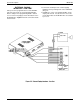
Make the following resistance measurements at the
station connector blocks under the following conditions.
•
AC power cord disconnected from electrical outlet.
•
Common equipment connected to station connector
blocks.
•
Stations wired, and wiring punched down on blocks.
•
Bridging clips removed from blocks to isolate stations
from common equipment.
1. Measure the resistance of each installed station and
wiring from the station side of the connector blocks.
Resistance values will vary with cable length and
station type but should be within the following limits.
MEASURED PAIR MEASURED STATION
RESISTANCE IN OHMS
VOICE PAIR 40 - 150
DATA PAIR 0.3 - 100
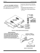
2. Measure the resistance of the common equipment
and cables from the common equipment side of the
station connector blocks. Resistance values should
be within the following limits.
MEASURED PAIR MEASURED COMMON
EQUIPMENT RESISTANCE
IN OHMS
VOICE PAIR 40 - 50
DATA PAIR 0.3 - 0.5
VOLTAGE CHECK
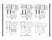
Refer to Table 3-3 and make the following voltage
measurements at the station connector blocks under
the following conditions:
•
Bridging clips installed
•
AC power connected to the common equipment
Measure the voltage across one voice line and one
data line and then across the other voice line and
the other data line for each even and odd station.
The measured voltage must be as follows:
GENERAL CHECK
1. Check the red light emitting diode (LED) system
status indicator. Be sure that it is on steady. If it
is off or flashing, disconnect and reconnect the
AC power plug.
2. Refer to the station User’s Guide for operating
information. Perform a general operational test of
the system by exercising the system features
from station port 10.
System Description IMI 66-064
3-17
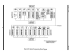
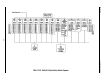
Table 3-3 Voltage Measurements
UNIT UNDER TEST
66-M-xx BLOCK
CONNECTION
METER LEAD
POLARITY
MEASURED
VOLTAGE
TYPICAL EVEN Voice 1 (+)
STATION Data 3 (-) +34 (+/-8) VDC
(Repeat for Voice 2 (+)
each even station) Data 4 (-) +34 (+/-8) VDC
TYPICAL ODD Voice 5 (+)
STATION Data 7 (-) +34 (+/-8) VDC
(Repeat for Voice 6 (+)
each odd station) Data 8 (-) +34 (+/-8) VDC
Variant readings can indicate a possible wiring, station, or common equipment
problem.