R ISO 9001 Certified XE Key System System Manual Printed in U.S.A. The information in this publication is applicable for the following common equipment: Manufacturing Code Model N0308 Rev J and later N0308-AT Rev J and later N0616 Rev J and later N0616-AT Rev J and later N0820 Rev M and later N0820-AT Rev M and later IMI66–064.
Comdial® strives to design the features in our communications systems to be fully interactive with one another. However, this is not always possible, as the combinations of accessories and features are too varied and extensive to insure total feature compatibility. Accordingly, some features identified in this publication will not operate if some other feature is activated.
Table of Contents IMI 66-064 iii
Table of Contents IMI 66-064 iv
IMI 66-064 Table of Contents v
This page remains blank intentionally.
System Description IMI 66-064 CHAPTER 1 SYSTEM DESCRIPTION SECTION 1 INTRODUCTION MANUAL SCOPE TAB059A-Software Enhancement This publication contains a complete description of the ExecuTech model XE electronic key system.
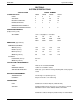
IMI 66-064 System Description SECTION 2 SYSTEM SPECIFICATIONS SPECIFICATION SYSTEM CAPACITY LINES: MODEL NUMBER N0308 3 N0616 6 N0820 8 N1024 10\\ STATIONS: 8 16 20 24 DSS/BLF CONSOLES: 4 8 20 24 INTERCOM PATHS: 1 3 3 2 1 3 3 2 MAXIMUM SIMULTANEOUS INTERCOM CONVERSATIONS: POWER REQUIREMENTS (Fullly loaded system) AC POWER: 117V +/- Singlephase - all models .4A .5A .8A. .8A 25W 45W 65W 65W 40VA 60VA 80VA 80VA WIDTH (inches): 10.4 13.1 15.6 15.
System Description IMI 66-064 MUSIC INTERFACE INPUT LEVEL: 3 Volts peak-to-peak maximum INPUT IMPEDANCE: Approximately 500 Ohms CONNECTOR: RCA phono jack CENTRAL OFFICE LIMITS LOOP LIMITS: 1,900 Ohms maximum loop CABLE INSULATION LEAKAGE: 15,000 Ohms minimum INDUSTRY REGULATORY STANDARDS FCC Certified, part 15 (Class A) FCC Registered (fully protected) UL listed (power supply only) EIA RS478 Bell publication 48002 guidance Hearing aid compatible handset MEMORY RETENTION AFTER POWER LOSS 30 ho
IMI 66-064 System Description SECTION 3 GENERAL INFORMATION CONFIGURATION A software upgrade kit is available for field installation. The EPROM chip supplied in this kit will revise the operating system software of the XE system to the latest factory issued level.
System Description • • • • IMI 66-064 32, are available as autodial locations at the first level of storage. For example, a model N1024 key system and a EB32X-xx or DB32-xx console will fix the first 24 console buttons as DSS/BLF buttons, and provide the remaining eight buttons as autodial buttons. Plus, it will provide autodial locations at the second level of storage for the first 24 buttons. A total of 32 autodial storage locations are provided.
IMI 66-064 System Description 1-6
System Description IMI 66-064 1-7
IMI 66-064 1-8 System Description
System Description 1-9 IMI 66-064
This page remains blank intentionally
System Description IMI 66-064 CHAPTER 2 DESCRIPTION OF SYSTEM FEATURES AUTO-SAVE FEATURE The auto-save feature can be used to save the last manually dialed number at any unprogrammed button or at a specific button that was previously reserved for this purpose. The button chosen for auto-save must be blank and not currently programmed as a DSS button, line select button, or auto dial button.
IMI 66-064 System Description appearance can gain access at the same time (sometimes known as common line pickup). A line is specified as private or non-private through system or administration programming. Also see the discussion titled, Add-on Conference And Privacy Release. BASIC KEY SERVICE (1A2) The system provides all of the basic, 1A2-type, key service features. These features are: selective line pickup, common line pickup, multiline pickup, and hold.
System Description IMI 66-064 COMMON AUDIBLE RINGER INTERFACE CALL TRANSFER - SCREENED Connections are available at the key service unit which provide “dry-contact” relay closures whenever an incoming line rings. These contact closures track the ringing pattern and can be used to control an external signalling device.
IMI 66-064 System Description programming can be used to program a line port as an external paging port. DSS/BLF CONSOLE (OPTIONAL) EXTENDED DUAL TONE MULTIPLE FREQUENCY (DTMF) TONES The DSS/BLF Console is designed to be a companion to any system station. It is useful with high call volumesystems which require a dedicated call transfer location. The console provides a one-button direct station selection (DSS) intercom and an associated busy lamp field (BLF).
System Description IMI 66-064 LCD SUPPORT automatically connect the station to any assigned line that is idle and has been arranged for this feature. The line button will not have to be pressed. This feature is mutually exclusive with prime line automatic. Programming for this feature is through either system or administration programming.
IMI 66-064 System Description speaker light flashes to indicate a muted condition. The button provides push-on/push-off operation. Also refer to the discussion titled, Handsfree Answer Inhibit. MESSAGE WAITING Special dialing codes enable a station user to control the message waiting (MW) light at other stations in the system. When the message waiting light is turned on at a station, a call can be placed to the originating station to pick up the message.
System Description IMI 66-064 AC power failure. The power-fail telephone is automatically disconnected as soon as power is restored. OPX SUPPORT The system supports the operation of the optional off premises extension (OPX) unit. System or administration programming arranges a station port for OPX operation. POWER ON, VISUAL INDICATION The common equipment has a red LED which monitors the status of the system, and provides an “AC power-on” indication.
IMI 66-064 System Description handset. Because the MUTE button is pressed, the distant party is prevented from hearing the response. PULL OUT DIRECTORY Each desk mounted telephone is equipped with a pull out directory. This directory can be used for recording the system speed dial, station speed dial, or other frequently called numbers. The system provides SOHVA operation at every station port; however, a station that has the voice announce blocking feature turned on cannot receive a SOHVA call.
System Description IMI 66-064 station will prevent it from calling a system speed dial number that matches the restrictions. Class of service programming or Administration programming can be used to enable or disable this feature. Refer to the discussions titled, System Speed Dial and Toll Restriction - Flexible. SINGLE-DIGIT STATION DIALING Refer to the discussion titled, System Speed Dial.
IMI 66-064 System Description Once programmed, flexible toll restriction is assigned on a per line/per station basis. In addition to flexible restriction, or as an alternative to it, stations can be restricted with 1/0 call restriction assignment. When 1/0 call restriction is selected, 1+ 7 digit dialing can be allowed if desired. Either system or administration programming is used to specify the deny and allow entries and assign the restriction to line and station.
System Description IMI 66-064 CHAPTER 3 INSTALLATION SECTION 1 STANDARD INSTALLATION DETAILS • MOUNTING CONSIDERATIONS • The common equipment cabinet should be attached vertically to any sturdy, flat, surface or vertically rack mounted if desired. • Cabinet must be located within four (4) feet of a proper electrical outlet. The system requires a dedicated 117VAC 15 AMP circuit, with a third-wire ground, supplied to a standard electrical outlet (NEMA 5-15R).
IMI 66-064 3-2 System Description
IMI 66-064 System Description AC POWER CONNECTION Employ a dedicated 117VAC 15 AMP circuit, with a third-wire ground, supplied to a standard electrical outlet (NEMA 5-15R) for the AC power connection. AC power connection is illustrated in Figure 3-2 shown below. • • • A plug-in power line surge protector should be installed between the power cord and the AC outlet. Do not connect the AC power cord until the installation has been checked.
IMI 66-064 System Description cable connected to the common equipment 50-pin male connectors. Table 3-2a shows the station connection detais. Station connections for the model N0308 are via standard modular plug/jack connections provided on the side of the common equipment cabinet. These jacks are labeled by station number. Table 3-2b details these connections. • The maximum distance allowed from the common equipment to the station when using #24 gauge, twisted-pair cable is 1500 feet.
System Description IMI 66-064 3-5
IMI 66-064 System Description 3-6
System Description IMI 66-064 3-7
IMI 66-064 3-8 System Description
System Description 3-9 IMI 66-064
IMI 66-064 System Description SECTION 2 OPTION INSTALLATION DETAILS DSS/BLF CONSOLE CONNECTION The optional DSS/BLF console may be installed at any station port (except port 10) to work in conjunction with a companion station connected to the adjacent port (e.g. port 10 for station and port 11 for console). Console port installation is illustrated in Figure 3-3a and 3-3b, shown on the previous pages.
System Description SECURE OFF-HOOK VOICE ANNOUNCE STATION The XE system supports the Secure Off-Hook Voice Announce (SOHVA) feature provided by telephones with the following product codes: 6714X-xx all revs. 6600E-xx Rev. B and later 6614E-xx Rev. D and later 6614T-xx Rev. C and later 6620E-xx Rev. D and later 6620T-xx Rev. I and later IMI 66-064 Two data-paired ports are required to provide SOHVA support. The SOHVA equipped telephones contain a 6-position, 3-pair line jack.
IMI 66-064 POWER FAILURE STATION The system provides one tip and ring pair connected to line one as an emergency, power failure circuit. This power failure pair is located on Mod jack 1 for all common equipment models. This jack is the rightmost jack when facing the right side of the cabinet as shown System Description in Figure 3-5. The power failure pair is only active during an AC power failure.
System Description COMMON AUDIBLE AND AUXILIARY STATION INTERFACE (STATION 17 AUDIBLE) IMI 66-064 • Two sets of relay closure dry-contact points are available. These are located at the J-1 and J-2 connector blocks for models N0616, N0820, and N1024 and at the barrier-type terminal strip on the model N0308 common equipment cabinet. These closures track the ringing pattern. They are closed during the ringing period and open during the silent period. Figure 3-6 shows connection details for this feature.
IMI 66-064 EXTERNAL PAGING INTERFACE STATION PA PORT Any station port can be programmed as a PA port and used to couple a station voice path to an external paging amplifier. Refer to Chapter for programming details. Figure 3-7 shows connection details for this feature.
System Description EXTERNAL PAGING INTERFACE - LINE PORT A line port can be programmed to be an AUXILIARY port and connected to an external paging amplifier. Refer to Chapter 4 for programming details. Station access to this area paging is via the line button for the AUXILIARY line. Figure 3-8 shows connection details for this feature. IMI 66-064 • • 3-15 Connect the audio input of an external paging amplifier to the tip and ring leads of the AUXILIARY (line) port.
IMI 66-064 AUXILIARY EQUIPMENT INTERFACE A non-key system telephone device or a data device can be connected ahead of the common equipment. Refer to Table 3-1 on page 3-4 and Figure 3-9 below for connection details for this feature. System Description The system can detect an off-hook condition in the connected device, and turn on the line status light at the button system telephones to indicate that the line is busy.
System Description IMI 66-064 SECTION 3 CHECKOUT AND FAILURE ISOLATION INSTALLATION CHECKOUT MEASURED PAIR RESISTANCE CHECK Make the following resistance measurements at the station connector blocks under the following conditions. VOICE PAIR DATA PAIR • • AC power cord disconnected from electrical outlet. Common equipment connected to station connector blocks. • Stations wired, and wiring punched down on blocks. • Bridging clips removed from blocks to isolate stations from common equipment. 1.
IMI 66-064 System Description FAILURE ISOLATION SYSTEM STATUS INDICATOR The red LED located near the fuse holder is the system status indicator. This indicator should turn on steady when AC power or the optional external battery power is applied to the common equipment. If the indicator flashes after power up, it could be indicating a processor failure. Unplug and reconnect the AC power, and observe the LED indication. If it still shows a flashing indication, equipment replacement may be necessary.
System Description IMI 66-064 SECTION 4 INSTALLER/USER INFORMATION REGARDING FCC RULES AND REGULATIONS PARTY LINES AND COIN LINES This electronic button system complies with Federal Communications Commission (FCC) Rules, Part 68. The FCC registration label on the KSU contains the FCC registration number, the ringer equivalence number, the model number, and the serial number or production date of the system.
IMI 66-064 the user should consult the manufacturer or an experienced radio/television technician for additional suggestions. The user may find the following booklet prepared by the Federal Communications Commission helpful: “How to Identify and Resolve Radio-TV Interference Problems.” This booklet is available from the Government Printing Office, Washington D.C. 20402. Stock No. 004-000-00345-4.
System Description IMI 66-064 CHAPTER 4 SYSTEM PROGRAMMING SECTION 1 INTRODUCTION System programming is divided into three categories: • • • It is recommended that a 14-line monitor telephone (such as mfg. code 6714X) be used for programming since it provides all needed program buttons and LED indicators for program status feedback. Class Of Service Programming: The class of service programming is unlimited as to the features that can be programmed using it.
IMI 66-064 4-2 System Description
System Description 4-3 IMI 66-064
IMI 66-064 4-4 System Description
System Description IMI 66-064 SECTION 2 CLASS OF SERVICE PROGRAMMING Class of service programming is usually performed by the system installer. Class of service programming procedures provide the means for programming all of the system variables including the master clear. The installer may elect to program only the line attributes and allow the remainder of the system variables to remain set to their default values. Perform class of service programming as shown below.
IMI 66-064 4-6 System Description
System Description 4-7 IMI 66-064
IMI 66-064 4-8 System Description
System Description 4-9 IMI 66-064
IMI 66-064 4-10 System Description
System Description 4-11 IMI 66-064
IMI 66-064 4-12 System Description
System Description 4-13 IMI 66-064
IMI 66-064 4-14 System Description
System Description 4-15 IMI 66-064
IMI 66-064 4-16 System Description
System Description 4-17 IMI 66-064
IMI 66-064 System Description SECTION 3 ATTENDANT PROGRAMMING Attendant programming ican be performed by from Station 10 at any time during system operation. NIGHT TRANSFER 5. Dial number (up to 15 digits). 6. Press TRANS/CONF button for next location and repeat procedure. -OR- (of ringing) The day, or normal, ringing of incoming lines can be transferred to a particular station or stations by the attendant for off-hour or special purpose answering. 1. Press ITCM * #. 2. Dial 03. 3. Press prog.
System Description IMI 66-064 CHAPTER 5 SYSTEM OPERATING PROCEDURES SECTION 1 STATION OPERATION ANSWERING CALLS To answer a call that is ringing at any station in system, ANSWERING OUTSIDE CALLS Calls appear at buttons that have actual line assignments. • • • • • Press line button of ringing line (line button with flashing light). Lift handset. Lift handset. Press ITCM. Dial # 4.
IMI 66-064 System Description MAKING CALLS • • • OUTSIDE LINE CALLING • Press line button to select line. NOTE: Selecting a line is not necessary if: NOTE: Some systems may be programmed to tone signal as the first option. Pressing ITCM a second time is not necessary in this case A priority line has been assigned to a telephone (prime line feature enabled). The telephone automatically picks an idle line for use when the handset is lifted (idle line preference feature enabled). • • Press ITCM.
System Description IMI 66-064 SPEED DIALING If call is answered, To dial station speed dial numbers, Take control by lifting handset. If control is not taken, call will drop. To cancel automatic redial, • • Press keypad digit 0 - 9 for desired personal speed dial number. -OR- • If on line listening to dial tone, • Press HOLD and then press desired keypad digit 0 - 9. NOTE: Any user-originated station activity during automatic redial will cancel the feature.
IMI 66-064 System Description • EXTENDED DTMF The length of the DTMF tone can be extended from the standard length to a pre-programmed longer length. • To extend tone length, • • Take station off-hook (lift handset). Press line button to select line if not automatically selected by going off-hook. Wait 10 seconds, and dial number.
System Description IMI 66-064 CONFERENCING • • • • Conference transmission levels are not compensated and are dependent upon the quality of the external lines. MULTILINE CONFERENCE (2 external parties, 1 internal party) To set up a multiline conference, • • • • ADD-ON CONFERENCE Establish first outside call. (Do not press HOLD.) Press TRANS/CONF. (Outside call is placed on hold automatically.) Establish second outside call. (Do not press HOLD.) Press TRANS/CONF. Conference is established.
IMI 66-064 System Description LINE MONITORING manner until the party returns, and then lift the station handset to resume the call. To activate while on a call, • • Press MNTR (SPKR). Monitor light will turn on. Hang up handset. To cancel, • NOTE: If a distant party places the call on hold, the station user can monitor in a handsfree • Lift handset to resume conversation -ORPress MNTR (SPKR) to disconnect. Monitor light will turn off.
System Description IMI 66-064 MUTE / HANDSFREE ANSWER INHIBIT The MUTE button is in a non-latching mode when the station handset is lifted and in a latching mode when the station is operated in a handsfree manner. • To prevent distant party from hearing while handset is lifted, To inhibit handsfree answer of intercom calls, • To resume two-way conversation, Release MUTE. Speaker light will turn off. • Press and latch MUTE. Speaker light will flutter.
IMI 66-064 System Description SPEAKERPHONE OPERATION (ExecuTech Model 6600S-xx and 6600E-xx Telephones Only) • The optional speakerphone can exercise the previously described features in a handsfree manner. Handsfree calling and call answering is as described below. To end a call, • To place a call, • • • Press line button or ITCM. Dial number or press programmable button. When party answers, speak toward the telephone. Press SPKR. To switch from speakerphone to handset, • Lift handset.
System Description IMI 66-064 STATION SPEED DIAL PROGRAMMING DIRECT STATION SELECTION/BUSY LAMP FIELD (DSS/BLF) PROGRAMMING Station speed dial numbers can be stored by the station user for later redial. The storage locations are keypad digits 0 through 9 on the station. Before attempting to program, decide on the following items: (1) the number or feature to be stored, (2) which storage location will be used (0 - 9), (3) the circuit that the call will go over (individual line or intercom).
IMI 66-064 System Description SECTION 2 ATTENDANT STATION OPERATION SYSTEM CLOCK If the system has been modified to provide LCD speakerphone support, the system clock can be programmed to maintain current date and time information in the display. The clock information is not displayed until the feature is programmed. 4. Dial two digits (01-12) for mo. 7. Dial two digits (00-59) for min. 1. Press ITCM. 8. Dial one digit (1-7) for day of week (Sun.=1, Sat.=7) 2. Dial * # 0 1. 9.
IMI 66-064 System Description 5-11
IMI 66-064 System Description SECTION 4 SYSTEM OPERATING CHARACTERISTICS FEATURE DIALING CODE NUMBERING PLAN 5-12
System Description IMI 66-064 RINGER VOLUME CONTROL Each station has a ringer volume control. Depending upon the model, the ringer control is located on the front edge, rear edge, or bottom of the telephone. Adjust the control lever to OFF, LOW or HIGH volume as desired. STATUS INDICATORS AND TONE SEQUENCES The following pages describe the light and ring patterns associated with system operation. NOTE: The values shown are typical. They are provided for illustration purposes only.
IMI 66-064 5-14 System Description
System Description 5-15 IMI 66-064
IMI 66-064 5-16 System Description
System Description 5-17 IMI 66-064
IMI 66-064 5-18 System Description
System Description 5-19 IMI 66-064
IMI 66-064 5-20 System Description
System Description 5-21 IMI 66-064
System Description IMI 66-064 CHAPTER 6 MAINTENANCE TECHNICAL ASSISTANCE AND REPAIR SERVICE Comdial P.O.
Publcatiion Index IMI 66-064 I-1
IMI 66-064 Publication Index I-2
Publication Index IMI 66-064 I-3