
User's Manual


INSTALLATION GUIDE FOR RX78V2F-B-AC
ENU STATUS : 1-0-0
Copyright - refer to title page
Page 6
0.2 INDEX TO FIGURES AND TABLES
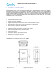
Figure 1: Front, Side and Bottom Views of the PS BDA Enclosure ................................................................. 11
Figure 2: PS BDA Functional Block Diagram................................................................................................... 13
Figure 3: Layout of the PS BDA ....................................................................................................................... 14
Figure 4: Mounting Rack Overview .................................................................................................................. 19
Figure 5: PS BDA Wall Mounting ..................................................................................................................... 20
Figure 6: Equipment Connectors ..................................................................................................................... 21
Figure 7: LED Indicators .................................................................................................................................. 22
Figure 8: Commissioning Procedure ................................................................................................................ 26
Figure 9: Input IP Address ............................................................................................................................... 28
Figure 10: Input Domain Name ........................................................................................................................ 28
Figure 11: Input User Name and Password ..................................................................................................... 28
Figure 12: Web GUI Main Screen .................................................................................................................... 29
Figure 13: Overview Screen............................................................................................................................. 29
Figure 14: External/Dry Contact ALM Screen .................................................................................................. 30
Figure 15: Channels Screen ............................................................................................................................ 30
Figure 16: Fast commission Screen ................................................................................................................ 31
Figure 17: Isolation Check Screen ................................................................................................................... 31
Figure 18: Reset/Import/Export Screen ........................................................................................................... 32
Figure 19: License Screen ............................................................................................................................... 32
Figure 20: Firmware Upgrade Screen .............................................................................................................. 33
Figure 21: Device Information Screen ............................................................................................................ 33
Figure 22: User Management Screen ............................................................................................................. 34
Figure 23: Alarm list ......................................................................................................................................... 38
Figure 24: Reset PA ......................................................................................................................................... 39
Table 1: Equipment Connectors ...................................................................................................................... 21
Table 2: LED Indicators .................................................................................................................................... 22
Table 3: Pin Definition of Dry Contact Cable ................................................................................................... 24
Table 4: Commissioning Task Explanation ...................................................................................................... 27