
User's Manual

MIRCU User Manual
© Comba Telecom Ltd. All Rights Reserved Page 21 of 24
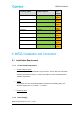
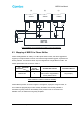
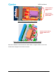
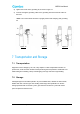
Figure 9 Mapping of MIRCU-S24 to Phase Shifter
6.4 MIRCU Control Cable, Lightning Protection and
Grounding cables
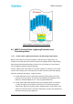
6.4.1 Control cable, Lightning Protection and Grounding requirements
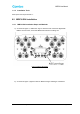
MIRCU control cable can connect through SBT or TMA (as shown in Figure 6 (b), (c)),
normally control cable will be short and not more than 2m, lighting protection and grounding
will be implemented along the RF feeder and hence it is not necessary for control cable to
carry out lightning Protection and grounding again.
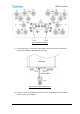
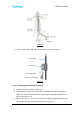
However, if MIRCU and control cable are connected as Figure 6 (a), whereby control cable
connect to RCU directly, then it is necessary for the cable control to proceed with Lightning
Protection and Ground requirement. Details as follows:
a) Control cables that connect to base station antenna should be within the scope of
protection of the air terminals. Air terminals shall establish special lightning current
deflectors, materials suitable are 4mm x 40 mm galvanized flat steel.
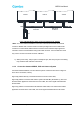
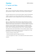
b) Control cables metal sheath should be clamp to grounding kit within 1m of antenna,
1m within the cable tray at the bottom of the tower, and 1m before entering base
station shelter. Make sure grounding cable is installed property, feeder window of the
shelter room should be close to the ground and properly connect to the grounding bar
that leads to the ground. (See Figure 10)