
User's Manual

MIRCU User Manual
© Comba Telecom Ltd. All Rights Reserved Page 18 of 24
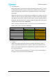
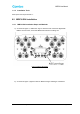
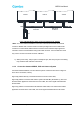
Figure 5 Multiple MIRCU Daisy-Chain Cascade Schematic Diagram
**Note: The control cables and MIRCU connectors at both ends were Male and Female
connector. MIRCU male connector used to receive Input Signal and connect with female
connector of control cables; MIRCU female connector used to transmit output signal and
cascade in series to another MIRCU using male cable connector. Control cables from PCU
only can be connect to the male connector of MIRCU.
e) Water proof: Firstly, wrap 3 layers of waterproof tape, then wrap 3 layers of insulating
tape, fastened with cable ties at both ends.
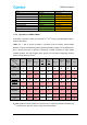
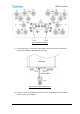
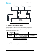
6.2.2 Connection between MIRCU, PCU and Antenna System
Connection between MIRCU, PCU and antenna system connections are shown in Figure 6.
There are 3 connections, namely:
Figure 6(a): MIRCU directly connected with the PCU via the control cable;
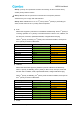
Figure 6(b): MIRCU connected with antenna system terminal SBT (Smart Bias-T), PCU and
the base station apparatus connected to the end of SBT, the control signal transmitted thru
the RF feeder.
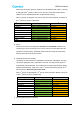
Figure 6(c): MIRCU connected with AISG interface enable TMA, PCU and the base station
apparatus connected to the end of SBT, the control signal transmitted thru the RF feeder.
PCU-H002
Antenna
PCU
Cable
AISG IN
AISG OUT
Antenna
AISG IN
AISG OUT
Antenna
AISG IN AISG OUT
Daisy Chain
Connection
Daisy Chain
Connection