
User's Manual


Page 14 of 25
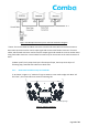
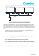
Figure 3-4 Multiple IRCU Daisy-Chain Cascade Schematic Diagram
**Note: The control cables and IRCU connectors at both ends were Male and Female connector.
IRCU male connector used to receive Input Signal and connect with female connector of control
cables; IRCU female connector used to transmit output signal and cascade in series to another IRCU
using male cable connector. Control cables from PCU only can be connect to the male connector of
IRCU.
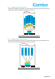
e) Water proof: Firstly wrap three layers of waterproof tape, then wrap three layers of
insulating tape, fastened with cable ties at both ends.
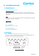
5.2.2 IRCU-C814 installation steps and methods
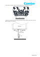
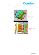
a) As shown in Figure 4-1, "AISG OUT" logo on Antenna cover need to align with IRCU “IN”
and “OUT”, then insert IRCU into antenna mounting slot.
Figure 4-1 IRCU Installation
IRCU-C814
AISG port logo