
User's Manual

INSTALLATION GUIDE FOR RX-7W22
ENU STATUS : 1-0-2
Copyright - refer to title page
Page 12
3.2.2 RF CABLE CONNECTION
AMS RF cables connection is as follows:
⚫ RF IN port → connect to BDA or Signal Booster’ MT or Service port
⚫ PF OUT port → connect to the passive system to the antennas
3.2.3 POWER CONNECTION
Connect the power cord to the DC48V power source
⚫ RED → connect to Positive
⚫ BLUE → connect to Negative
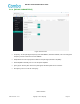
3.2.4 ETHERNET CONNECTION
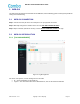
Establish an Ethernet connection using the ‘ETH’ port located on the panel.
3.2.5 DRY CONTACT CABLE CONNECTION
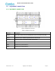
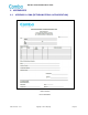
Below please find the pin definitions of the dry contact cables. (same for both ALM1 and ALM2 ports)
Table 2: Pin Definition of Dry Contact Cables
Pin NO.
Pin
Description
Color Code
ALM
1
CLOSE
Dry Contact Alarm
RED
2
COM
Dry Contact Alarm
BLUE
3
OPEN
Dry Contact Alarm
YELLOW