
User's Manual


INSTALLATION GUIDE FOR UHF DAS
ENU STATUS : 1-0-0
Copyright - refer to title page
Page 16
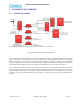
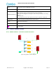
OMT
RJ45 Connector for local WEB GUI connection.
OP
Optical port, connect to Expansion Unit
PWR/RUN/FUNC/OP
LED indictor
PWR: ON: Power supply is normal; OFF: Power supply is abnormal.
RUN: Regular Flashing: RU is working fine; OFF or Always ON: RU is not working
properly
FUNC: Reserved
OP: ON: Optical link is fine; OFF: Optical link is broken, optical TX or RX alarm
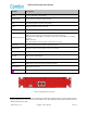
MT/DL OUT
N-Female connector for connection to the service antenna.
UL IN
Input port for Uplink Signal
IN1-4/OUT1-4
Reserved
Ground terminal
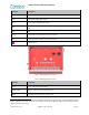
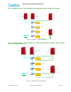
2.5 TYPICLA APPLICATION
2.5.1 APPLICATION 1: ONE MU CONNECTS 32 RUS.
OP1 OP2 OP3 OP4
OP5 OP6 OP7 OP8
DL1
UL1 DL2 UL2
DL_E
UL_E
OP1 OP2 OP3 OP4
OP5 OP6 OP7 OP8
DL1
UL1 DL2 UL2
DL_E
UL_E
OP1 OP2 OP3 OP4
OP5 OP6 OP7 OP8
DL1
UL1 DL2 UL2
DL_E
UL_E
OP1 OP2 OP3 OP4
OP5 OP6 OP7 OP8
DL1
UL1 DL2 UL2
DL_E
UL_E
RU1
EU
MU
RU32
RF Cable
Fiber
EU1
EU2
EU3
EU4
Figure 8: Application 1 System Diagram