
User`s manual


RTD Embedded Technologies, Inc. | www.rtd.com iv COM16155ER/COM16155RER User’s Manual
Table of Contents
1 Introduction 7
1.1 Product Overview........................................................................................................................................................................ 7
1.2 Board Features ........................................................................................................................................................................... 7
1.3 Ordering Information ................................................................................................................................................................... 8
1.4 Contact Information .................................................................................................................................................................... 8
1.4.1 Sales Support 8
1.4.2 Technical Support 8
2 Specifications 9
2.1 Operating Conditions .................................................................................................................................................................. 9
2.2 Electrical Characteristics ............................................................................................................................................................ 9
3 Board Connection 10
3.1 Board Handling Precautions ..................................................................................................................................................... 10
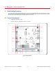
3.2 Physical Characteristics ............................................................................................................................................................ 10
3.3 Connectors and Jumpers .......................................................................................................................................................... 11
3.3.1 External I/O Connectors 11
CN8: Digital I/O Connector 11
CN6: SIM Module/Connector 11
CN7: GSM Headset Connector 12
3.3.2 Jumpers 13
JP6 & JP7: Base Address Jumpers 13
JP3: GPS Interrupt Jumper 15
3.3.3 Solder Blob Jumpers 15
3.3.4 LED Indicators 15
D1 – SIM card Power 15
D3 – 1 PPS 16
D4 – GSM STATUS Signal 16
3.4 Steps for Installing .................................................................................................................................................................... 17
4 IDAN Connections 18
4.1 Module Handling Precautions ................................................................................................................................................... 18
4.2 Physical Characteristics ............................................................................................................................................................ 18
4.3 Connectors................................................................................................................................................................................ 18
4.3.1 External I/O Connectors 18
Digital I/O Connector 18
Headset Connector 19
4.4 Steps for Installing .................................................................................................................................................................... 20
5 Functional Description 21
5.1.1 Cinterion MC55i-W Quad-Band Cellular Engine (COM16155ER) 21
MC55i-W Module Interface 22
GSM Antenna Considerations 22
SIM-Card Reader 22
5.1.2 Linx RXM-GNSS-TM GPS Receiver 22
GPS module interface 23
GPS Antenna 23
5.1.3 Digital I/O 23
6 Register Address Space 24
6.1 General Board Control .............................................................................................................................................................. 24
6.1.1 UART I/O (GPS/GSM BASE + 0 to GPS/GSM BASE + 7) 25
6.1.2 GSM Status (GSM BASE +402h) 25
6.1.3 GSM Control (GSM BASE +403h) 25
6.1.4 GPS Status (GPS BASE + 401h) 25