
User`s manual


RTD Embedded Technologies, Inc. | www.rtd.com 27 COM16155ER/COM16155RER User’s Manual
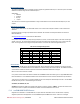
Table 20: RTD ID DATA READ Indexes
Index
Data
8-Bit Read
16-Bit Read
13
Board Name String
1
—
14
Board Name String
6
61
15
Board Name String
1
—
16
5
55
17
5
—
18
Board Name String
<nul>
<nul><nul>
19
Board Name String
<nul>
—
20–255
Unused
FFh
FFFFh
6.2 COM17045 Compatibility
This register is intended only for COM17045 compatibility. This address is used to interface to the digital I/O port of the COM16155. Writing to
this address will transfer the data to the output port, while reading from this address will return the data from the digital inputs. This register is
compatible with the COM17045 module. Note the default direction of the 16 digital I/O bits is bits 0 - 7 are outputs and 8 - 15 are inputs. Note:
If you change the direction registers from the default, then this register will not operate properly.
Table 21: Digital I/O Data (GPS BASE + 400h)
Write
BIT
FUNCTION
DIRECTION
Bit 0
Output 0
CN8 Pin 2
Bit 1
Output 1
CN8 Pin 3
Bit 2
Output 2
CN8 Pin 4
Bit 3
Output 3
CN8 Pin 5
Bit 4
Output 4
CN8 Pin 6
Bit 5
Output 5
CN8 Pin 7
Bit 6
Output 6
CN8 Pin 8
Bit 7
Output 7
CN8 Pin 9
Table 22: Digital I/O Data (GPS BASE + 400h)
Read
BIT
FUNCTION
DIRECTION
Bit 0
Input 0
CN8 Pin 12
Bit 1
Input 1
CN8 Pin 13
Bit 2
Input 2
CN8 Pin 14
Bit 3
Input 3
CN8 Pin 15
Bit 4
Input 4
CN8 Pin 16
Bit 5
Input 5
CN8 Pin 17
Bit 6
Input 6
CN8 Pin 18
Bit 7
Input 7
CN8 Pin 19
6.3 Using the GSM Engine
The GSM engine is controlled via the industry-standard ASCII ‘AT’ command set. A user can operate the GSM simply by sending it command
strings from a terminal emulator program (e.g. Windows HyperTerminal).
The complete list of AT command strings supported by the MC55i-W are described in a document provided by Cinterion. Refer to the
Additional Information section of this manual for more information.
6.3.1 STARTING UP AND LOGGING INTO THE GSM NETWORK
With no power applied insert your +3V or dual voltage SIM into the card- holder on the solder side of the board. Connect the antenna cable to
the MC55i-W antenna connector and power up your PC/104 system. The COM16155 will be initialized by the system. After this the status LED
will blink for a while until the MC55i-W is logged into the network. If you have the PIN code enabled, the COM16155 status LED will continue to
blink until the PIN code is given through the terminal mode with AT command AT+CPIN”XXXX”, unless AT^SFLC (facility lock for PIN code)
has been set. Once the COM16155 is logged onto the network the LED will be lit continuously.
6.3.2 USING SMS
The SMS features of the Cinterion MC55i-W are controlled by AT command strings. The Cinterion documentation covers these commands in
depth.