
User`s manual


RTD Embedded Technologies, Inc. | www.rtd.com 26 COM16155ER/COM16155RER User’s Manual
6.1.5 DIGITAL I/O
COM16155 allows bit programmable direction for all digital I/O bits. COM17045 compatibility is described later. Note the digital I/O registers
are accessed at 404h – 407h above the GPS/GSM COM port. These addresses are used to interface to the digital I/O port. The 16 bits each
have a direction bit. If the direction bit is set to output, a value written to the data bit is provided on the connector. A read will result in the value
on the connector pin (i.e. the output value). If the direction is set to input, a value written to the data bit is ignored and a read will result in the
value on the connector pin.
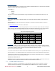
Table 16: Digital I/O Data (GPS/GSM BASE + 404h)
Default: 0x00
BIT
FUNCTION
DIRECTION
Bit 0
DIO0
CN8 Pin 2
Bit 1
DIO1
CN8 Pin 3
Bit 2
DIO2
CN8 Pin 4
Bit 3
DIO3
CN8 Pin 5
Bit 4
DIO4
CN8 Pin 6
Bit 5
DIO5
CN8 Pin 7
Bit 6
DIO6
CN8 Pin 8
Bit 7
DIO7
CN8 Pin 9
Table 17: Digital I/O Data (GPS/GSM BASE + 405h)
Default: 0x00
BIT
FUNCTION
DIRECTION
Bit 0
DIO8
CN8 Pin 12
Bit 1
DIO9
CN8 Pin 13
Bit 2
DIO10
CN8 Pin 14
Bit 3
DIO11
CN8 Pin 15
Bit 4
DIO12
CN8 Pin 16
Bit 5
DIO13
CN8 Pin 17
Bit 6
DIO14
CN8 Pin 18
Bit 7
DIO15
CN8 Pin 19
Table 18: Digital I/O Direction (GPS/GSM BASE + 406h)
Default: 0xFF
BIT
FUNCTION
DIRECTION
Bit 0
DIO0
0 = INPUT
1 = OUTPUT
Bit 1
DIO1
0 = INPUT
1 = OUTPUT
Bit 2
DIO2
0 = INPUT
1 = OUTPUT
Bit 3
DIO3
0 = INPUT
1 = OUTPUT
Bit 4
DIO4
0 = INPUT
1 = OUTPUT
Bit 5
DIO5
0 = INPUT
1 = OUTPUT
Bit 6
DIO6
0 = INPUT
1 = OUTPUT
Bit 7
DIO7
0 = INPUT
1 = OUTPUT
Table 19: Digital I/O Direction (GPS/GSM BASE + 407h)
Default: 0x00
BIT
FUNCTION
DIRECTION
Bit 0
DIO8
0 = INPUT
1 = OUTPUT
Bit 1
DIO9
0 = INPUT
1 = OUTPUT
Bit 2
DIO10
0 = INPUT
1 = OUTPUT
Bit 3
DIO11
0 = INPUT
1 = OUTPUT
Bit 4
DIO12
0 = INPUT
1 = OUTPUT
Bit 5
DIO13
0 = INPUT
1 = OUTPUT
Bit 6
DIO14
0 = INPUT
1 = OUTPUT
Bit 7
DIO15
0 = INPUT
1 = OUTPUT
6.1.6 RTD ISA ID
RTD ID is a method to identify a board on the ISA bus. There are two 8-bit registers mapped at BA + 800h and BA + 801h. The registers
can be read as two 8-bit or one 16-bit. An internal pointer is auto-incremented with every read to either address so the data read will step
through each index as indicated below. The pointer is set to zero at reset and can be reset to zero by a read to BA + 802h.
Table 20: RTD ID DATA READ Indexes
Index
Data
8-Bit Read
16-Bit Read
0
Device ID
55h
6155h
1
Device ID
61h
—
2
RTD Vendor ID
35h
1435h
3
RTD Vendor ID
14h
—
4
EPLD Revision
Revision
LSD
Revision
5
EPLD Revision
Revision
MSD
—
6–9
Reserved
Ignore
Ignore
10
Board Name String
C
CO
11
Board Name String
O
—
12
Board Name String
M
M1