
User`s manual


RTD Embedded Technologies, Inc. | www.rtd.com 25 COM16155ER/COM16155RER User’s Manual
6.1.1 UART I/O (GPS/GSM BASE + 0 TO GPS/GSM BASE + 7)
These are the UART registers for the GPS/GSM module. These resources are not described in detail, since they are mapped as a standard
PC serial port. For more details on the EXAR 16C550 UART chip programming please download the component specific data from the website:
http://www.exar.com.
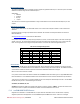
6.1.2 GSM STATUS (GSM BASE +402H)
Table 13: GSM STATUS (GSM BASE + 402h)
Default: 0x00
BIT
FUNCTION
DIRECTION
COMMENTS
Bit 0
/EN_RST
Read
0 – GSM active
1 – Reset GSM in reset
Bit 1
/EN_INT
Read/Write
GSM interrupt enabled 1- disabled
Bit 2
TEMP_LOW
Read
1 – Board temperature below -20C
Bit 3
TEMP_HIGH
Read
1 – Board temperature over +70C
Bit 4
Reserved
Bit 5
Reserved
Bit 6
Reserved
Bit 7
Reserved
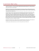
6.1.3 GSM CONTROL (GSM BASE +403H)
Table 14: GSM Control (GSM BASE + 403h)
Default: 0x00
BIT
FUNCTION
DIRECTION
COMMENTS
Bit 0
Ignition Signal
Read/Write
State of Ignition
1 -> 0 – Results in IGN signal
Bit 1
Power down
Read/Write
0 – Power On
1 – Power Down
Bit 2
Reserved
Bit 3
Reserved
Bit 4
Reserved
Bit 5
Reserved
Bit 6
Reserved
Bit 7
Reserved
6.1.4 GPS STATUS (GPS BASE + 401H)
Table 15: GPS STATUS (GPS BASE + 401h)
Default: 0x00
BIT
FUNCTION
DIRECTION
COMMENTS
Bit 0
Reserved
Bit 1
Reserved
Bit 2
Reserved
Bit 3
/EN_INT
Read/Write
0 = GPS interrupts enabled
1 = Disabled
Bit 4
Reserved
Bit 5
Reserved
Bit 6
1PPS/DIO 0
Read/Write
0 = DIO 0
1 = 1PPS
Bit 7
1 PPS
Read
1 PPS from GPS
Note: To output 1 PPS out DIO0, DIO0 direction needs set to an output.