
User`s manual


RTD Embedded Technologies, Inc. | www.rtd.com 22 COM16155ER/COM16155RER User’s Manual
MC55i-W Module Interface
The COM16155 GPRS/GSM modem is connected to the host computer through dedicated ISA serial port. The first serial port is connected to
GSM ASC0. The default configuration for the GSM serial ports is:
GSM Interface
9600 baud
8 data bits
No parity
1 stop bit
The modem can also connect through the USB interface. Simply load the USB driver and connect the USB to the USB port on your host
computer.
GSM Antenna Considerations
Typically standard GSM antennas use a female FME connector. This connector needs an adapter unit before it can be connected to the
COM16155.
RTD recommends the use of high quality antennas with the COM16155. We have tested successfully with antennas from Hirschmann
Rheinmetall Elektronik.
Visit http://www.hirschmann.de/ for information on GSM antennae.
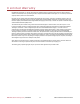
A very useful AT command that shows quality of the signal reception is: AT+CSQ. The format of the response is AT+CSQ: received signal
strength, bit error rate. The received signal strength shows the quality of the network signal and ranges from 0 to 31 as shown in the table
below. A value of greater than 10 should give an acceptable connection. The bit error rate number will range between 0 and 7.
Table 10: Received Signal Strength Values
99 = undetectable signal
0
- 113 dBm
8
- 97 dBm
16
- 81 dBm
24
- 65 dBm
1
- 111 dBm
9
- 95 dBm
17
- 79 dBm
25
- 63 dBm
2
- 109 dBm
10
- 93 dBm
18
- 77 dBm
26
- 61 dBm
3
- 107 dBm
11
- 91 dBm
19
- 75 dBm
27
- 59 dBm
4
- 105 dBm
21
- 89 dBm
20
- 73 dBm
28
- 57 dBm
5
- 103 dBm
13
- 87 dBm
21
- 71 dBm
29
- 55 dBm
6
- 101 dBm
14
- 85 dBm
22
- 69 dBm
30
- 53 dBm
7
- 99 dBm
15
- 83 dBm
23
- 67 dBm
31
=> - 51 dBm
SIM-Card Reader
Standard 3V and 1.8V SIM-cards can be used with the COM16155. Older 5V SIM cards will not work, though they may operate in standard
GSM cellular phones. The SIM-card holder has a card detection circuit that will in theory allow removal of the card. This is NOT recommended,
since the SIM card contents can become corrupted if it is removed while the MC55i-W GSM modem is writing to it.
LED D1 will turn on when a SIM card is enabled.
A very useful AT command that shows detection of the SIM card is: AT^SCID. The SIM card identifier is given as a reply ^SCID: value shows
the ID of the SIM card. If no ID is detected the MC55i-W cannot read the SIM card and cannot connect to the GSM service provider network.
To add an entry to your SIM card you may use the AT+CPBW command. In this example we add the RTD phone number +1-814-234-8087 to
the SIM card memory location “1” with the following AT command set:
AT+CPBW=1, 18142348087, 145, RTD
AT+CREG? Will indicate if the COM16155 is logged into the network. If the reply for example is +CREG: 0, 1 it means that connection to the
home network is valid. A complete AT-instruction set documentation is included in the MC55i-W user’s manual.
5.1.2 LINX RXM-GNSS-TM GPS RECEIVER
Integrated on the COM16155 is a Linx RXM-GNSS-TX, a low power fast-fix 33-channel GPS receiver. This GPS receiver is especially
designed for portable and mobile applications. The Linx RXM-GNSS-TM provides NMEA-0183 version 4.10 data and a 1 PPS signal.