
User`s manual


RTD Embedded Technologies, Inc. | www.rtd.com 13 COM16155ER/COM16155RER User’s Manual
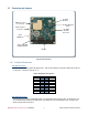
3.3.2 JUMPERS
The following sections describe the jumper configuration options available on the COM16155. The default factory jumper settings are listed in
the following table:
Table 7: Jumper Settings
Jumper
Description
Jumper Settings
Default Factory Setting
JP1
GPS Active Antenna Power
1-2: +5.0V
2-3: +3.3V
Open for passive antennas
1-2
JP2
GSM Interrupt Jumper
Set GSM Interrupt
5 and G
JP3
GSP Interrupt Jumper
Set GPS Interrupt
11 and G
JP4
Pull-up or Pull-down for DIO0-7
1-2: Pull-up
2-3: Pull-down
No connect – Neither
2-3
JP5
Pull-up or Pull-down for DIO8-15
1-2: Pull-up
2-3: Pull-down
No connect – Neither
2-3
JP6
GPS Base Address Jumper
Sets GPS Address
2E8
JP7
GSM Base Address Jumper
Sets GSM Address
3E8
JP8
COM16155/COM17045 Mode
1-2: COM17045 Compatible
2-3: COM16155
2-3
JP9
1PPS on UART carrier detect
(COM16155 mode only)
1-2: Enables 1PPS on UART CD
2-3: Disable 1PPS on UART CD
2-3
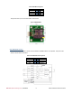
JP6 & JP7: Base Address Jumpers
The base address selection jumpers (A3 through A8) allow you to set the base address of the first UART that connects to the GPS module and
the second UART that connects to the GSM module. Any software that accesses the board will do so through reads and writes to the I/O
address set by the jumpers. To function properly, the I/O address the software is expecting must match the base address set by the jumpers.
As shown in the figure below, A3 is located at the left end of the jumper block, while A8 is located at the right end:
The table on the following pages shows the possible base address settings for the COM16155. All base addresses are in hexadecimal. An ‘X’
indicates a closed jumper, while an empty cell indicates an open jumper.
Base Address
(Hexadecimal)
Jumpers
A8
A7
A6
A5
A4
A3
200
208
X
210
X
218
X
X
220
X
228
X
X
230
X
X
238
X
X
X
240
X
248
X
X
250
X
X