
User`s manual


RTD Embedded Technologies, Inc. | www.rtd.com 11 COM16155ER/COM16155RER User’s Manual
3.3 Connectors and Jumpers
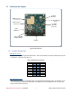
Figure 2: Board Connections
3.3.1 EXTERNAL I/O CONNECTORS
CN8: Digital I/O Connector
The COM16155 offers 16 bit-programmable digital I/O lines. These can be pulled high or low through 10KΩ resistors using JP4
to control bits 0 – 7 and JP5 to control bits 8 – 15
Table 4: CN7 Digital I/O Pin Assignments
DIO0
2
1
GND
DIO2
4
3
DIO1
DIO4
6
5
DIO3
DIO6
8
7
DIO5
+5V
10
9
DIO7
DIO8
12
11
GND
DIO10
14
13
DIO9
DIO12
16
15
DIO11
DIO14
18
17
DIO13
+5V
20
19
DIO15
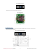
CN6: SIM Module/Connector
The COM16155 can use either an onboard SIM module or an external SIM connected through a cable. The COM16155-1 uses
an on-board SIM module and will not have CN4 installed. The COM16155-2 uses an external SIM module. The pinout of the
external connector CN6 is shown below.
ISA Bus
CN8:
Digital I/O
J3: GPS
Antenna
JP4 & JP5: DIO
Pullup/Pulldown
J2: GSM
Antenna
Connector
SIM Card socket
or connector
CN4
J5: GPS Antenna
Power
CN5: Headset
Connector