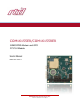
COM16155ER/COM16155RER GSM/GPRS Modem and GPS PCI/104 Module User’s Manual BDM-610020119 Rev. B RTD Embedded Technologies, Inc.
RTD Embedded Technologies, Inc. 103 Innovation Boulevard State College, PA 16803 USA Telephone: 814-234-8087 Fax: 814-234-5218 www.rtd.com sales@rtd.com techsupport@rtd.
Revision History Rev A Rev B Initial Release Corrected description of Triorail Module as Tri-Band instead of Quad-Band Corrected SIM-Card Reader section title Advanced Analog I/O, Advanced Digital I/O, aAIO, aDIO, a2DIO, Autonomous SmartCal, “Catch the Express”, cpuModule, dspFramework, dspModule, expressMate, ExpressPlatform, HiDANplus, “MIL Value for COTS prices”, multiPort, PlatformBus, and PC/104EZ are trademarks, and “Accessing the Analog World”, dataModule, IDAN, HiDAN, RTD, and the RTD logo are reg
Table of Contents 1 2 3 4 Introduction 7 1.1 Product Overview........................................................................................................................................................................ 7 1.2 Board Features ........................................................................................................................................................................... 7 1.3 Ordering Information ...................................................
6.1.5 6.1.6 7 9 26 26 6.2 COM17045 Compatibility .......................................................................................................................................................... 27 6.3 Using the GSM Engine ............................................................................................................................................................. 27 6.3.1 Starting up and logging into the GSM network 27 6.3.2 Using SMS 27 Troubleshooting 7.
Table of Figures Figure 1: Board Dimensions ................................................................................................................................................................................... 10 Figure 2: Board Connections .................................................................................................................................................................................. 11 Figure 3: ESIM2035 Board ..................................................
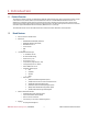
1 Introduction 1.1 Product Overview The COM16155 is designed to provide quad-band GSM and GPRS with global positioning system (GPS) for PCI/104 based systems. Included on the COM16155 are a Cinterion MC55i-W quad band GSM cellular modem and a Linx RXM-GNSS-TM GPS Receiver module. The COM16155 has an ISA UART chip that permits communication with serial port on the GSM as well as the serial port on the GPS receiver module over the PCI/104 bus without using other serial ports in the PC/104 system.
o Optional 1PPS on DIO0 PCI/104 compliant 1.
2 Specifications 2.1 Operating Conditions Table 2: Operating Conditions Symbol Vcc5 Vcc3 Vcc12 Ta Ts RH Parameter 5V Supply Voltage 3.3V Supply Voltage 12V Supply Voltage Operating Temperature Storage Temperature Relative Humidity MTBF Mean Time Before Failure Test Condition Non-Condensing Telcordia Issue 2 30°C, Ground benign, controlled Min 4.75 n/a n/a -30 -40 0 Max 5.25 n/a n/a +70 +85 90% TBD Unit V V V C C % Hours 2.
3 Board Connection 3.1 Board Handling Precautions To prevent damage due to Electrostatic Discharge (ESD), keep your board in its antistatic bag until you are ready to install it into your system. When removing it from the bag, hold the board at the edges, and do not touch the components or connectors. Handle the board in an antistatic environment, and use a grounded workbench for testing and handling of your hardware. 3.2 Physical Characteristics Weight: Approximately 80 g (0.18 lbs.
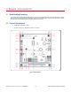
3.3 Connectors and Jumpers J3: GPS Antenna SIM Card socket or connector CN4 CN5: Headset Connector J5: GPS Antenna Power J2: GSM Antenna Connector CN8: Digital I/O JP4 & JP5: DIO Pullup/Pulldown ISA Bus Figure 2: Board Connections 3.3.1 EXTERNAL I/O CONNECTORS CN8: Digital I/O Connector The COM16155 offers 16 bit-programmable digital I/O lines.
Table 5: CN6 SIM Pin Assignment Vcc GND GND Card Detect GND 2 4 6 8 10 1 3 5 7 9 GND Reset I/O CLK Vcc The figure below shows a picture of the external SIM card interface board. Figure 3: ESIM2035 Board CN7: GSM Headset Connector The COM16155 Headset connector is used to connect a headset to the GSM module for voice operation. The pin-out of the external connector CN5 is shown below. Table 6: CN7 GSM Headset Pin Assignment MICP EPP VMICP Reserved GND RTD Embedded Technologies, Inc. | www.rtd.
3.3.2 JUMPERS The following sections describe the jumper configuration options available on the COM16155.
Base Address (Hexadecimal) 258 260 268 270 278 280 288 290 298 2A0 2A8 2B0 2B8 2C0 2C8 2D0 2D8 2E0 2E8 2F0 2F8 300 308 310 318 320 328 330 338 340 348 350 358 360 368 370 378 380 388 390 398 3A0 3A8 3B0 3B8 3C0 3C8 3D0 3D8 3E0 3E8 3F0 3F8 A8 A7 Jumpers A6 A5 X X X X X X X X X X X X X X X X X X X X X X X X X X X X X X X X X X X X X X X X X X X X X X X X X X X X X X X X X A4 A3 X X X X X X X X X X X X X X X X X X X X X X X X X X X X X X X X X X X X X X X X X X X X X X X X X X X X X X X X
When selecting a base address for the COM16155, please observe the following guidelines: Every device in your PC/104 system must have a unique base address! When selecting a base address for the COM16155, make certain that it does not conflict with any other devices. Base addresses 0x3F8 and 0x2F8 are typically used by serial ports COM1 and COM2, respectively. If you wish to use one of those base addresses, you will need to disable any conflicting serial port.
On when the SIM card is being powered from the cellular module D3 – 1 PPS Provides 1 PPS to LED, begins to flash once GPS has satellite fix. D4 – GSM STATUS Signal The GSM AT^SSYNC command serves to configure the STATUS pin of the application interface. The pin can either be used to indicate the current consumption in a transmit burst (default setting) or to drive a status LED connected to the pin. See the AT^SSYNC command for details. RTD Embedded Technologies, Inc. | www.rtd.
3.4 Steps for Installing 1. 2. 3. 4. 5. 6. 7. 8. 9. 10. 11. 12. Always work at an ESD protected workstation, and wear a grounded wrist-strap. Turn off power to the PC/104 system or stack. Select and install stand-offs to properly position the module on the stack. Remove the module from its anti-static bag. Check that pins of the bus connector are properly positioned. Check the stacking order; make sure all of the busses used by the peripheral cards are connected to the cpuModule.
4 IDAN Connections 4.1 Module Handling Precautions To prevent damage due to Electrostatic Discharge (ESD), keep your module in its antistatic bag until you are ready to install it into your system. When removing it from the bag, hold the module by the aluminum enclosure, and do not touch the components or connectors. Handle the module in an antistatic environment, and use a grounded workbench for testing and handling of your hardware. 4.2 Physical Characteristics Weight: Approximately 0.21 Kg (0.
Connector Part #: Amp 747913-2 Sample Mating Connector: Amp 3-1740199-2 Table 8: IDAN- COM16155 25-Pin Subminiature "D" Connector IDAN Pin# 1 2 3 4 5 6 7 8 9 10 11 12 13 4 15 16 17 18 19 20 21 22 23 24 25 DM35425 Pin # CN8 1 CN8 3 CN8 5 CN8 7 CN8 9 CN8 11 CN8 13 CN8 15 CN8 17 CN8 19 CN8 2 CN8 4 CN8 6 CN8 8 CN8 10 CN8 12 CN8 14 CN8 16 CN8 18 CN8 20 Reserved Reserved Reserved Reserved Reserved Signal GND DIO1 DIO3 DIO5 DIO7 GND DIO9 DIO11 DIO13 DIO15 DIO0/1PPS DIO2 DIO4 DIO6 +5V DIO8 DIO10 DIO12 DIO14 +
4.4 Steps for Installing 1. 2. 3. 4. 5. 6. 7. 8. 9. 10. 11. 12. Always work at an ESD protected workstation, and wear a grounded wrist-strap. Turn off power to the IDAN system. Remove the module from its anti-static bag. Check that pins of the bus connector are properly positioned. Check the stacking order; make sure all of the busses used by the peripheral cards are connected to the cpuModule.
5 Functional Description 5.1 Block Diagram The Figure below shows the functional block diagram of the COM16115. The various parts of the block diagram are discussed in the following sections. Headset ISA BUS ISA UART GSM Module GPS Antenna Interrupts SIM Linx GPS EPLD Control Logic GPS Antenna Digital I/O Connector CN7 Figure 7: COM16155 Block Diagram 5.1.
MC55i-W Module Interface The COM16155 GPRS/GSM modem is connected to the host computer through dedicated ISA serial port. The first serial port is connected to GSM ASC0. The default configuration for the GSM serial ports is: GSM Interface 9600 baud 8 data bits No parity 1 stop bit The modem can also connect through the USB interface. Simply load the USB driver and connect the USB to the USB port on your host computer.
A complete list of NMEA Messages and command messages is available from the manufacturer’s website at www.linxtechnologies.com. GPS module interface The RXM-GNSS-TM GPS is connected to the host computer through a dedicated ISA serial port. Carrier Detect of the serial port is driven by the 1 PPS signal.
6 Register Address Space This chapter shows you how to program and use your COM16155. It provides a general description of the I/O map. 6.1 General Board Control The memory map of the COM16155 occupies two groups of eight bytes of host PC I/O space. This window is freely selectable by the user by jumpers JP6 for GPS BASE and JP7 for the GSM BASE. After setting the base address you have access to the internal resources of the COM16155 control logic.
6.1.1 UART I/O (GPS/GSM BASE + 0 TO GPS/GSM BASE + 7) These are the UART registers for the GPS/GSM module. These resources are not described in detail, since they are mapped as a standard PC serial port. For more details on the EXAR 16C550 UART chip programming please download the component specific data from the website: http://www.exar.com. 6.1.2 GSM STATUS (GSM BASE +402H) BIT Bit 0 Bit 1 Bit 2 Bit 3 Bit 4 Bit 5 Bit 6 Bit 7 6.1.
6.1.5 DIGITAL I/O COM16155 allows bit programmable direction for all digital I/O bits. COM17045 compatibility is described later. Note the digital I/O registers are accessed at 404h – 407h above the GPS/GSM COM port. These addresses are used to interface to the digital I/O port. The 16 bits each have a direction bit. If the direction bit is set to output, a value written to the data bit is provided on the connector. A read will result in the value on the connector pin (i.e. the output value).
Index 13 14 15 16 17 18 19 20–255 Table 20: RTD ID DATA READ Indexes Data 8-Bit Read 16-Bit Read Board Name String 1 — Board Name String 6 61 Board Name String 1 — 5 55 5 — Board Name String Board Name String — Unused FFh FFFFh 6.2 COM17045 Compatibility This register is intended only for COM17045 compatibility. This address is used to interface to the digital I/O port of the COM16155.
7 Troubleshooting If you are having problems with your system, please try the following initial steps: Simplify the System – Remove modules one at a time from your system to see if there is a specific module that is causing a problem. Perform you troubleshooting with the least number of modules in the system possible. Swap Components – Try replacing parts in the system one at a time with similar parts to determine if a part is faulty or if a type of part is configured incorrectly.
8 Additional Information 8.1 PC/104 Specifications A copy of the latest PC/104 specifications can be found on the webpage for the PC/104 Embedded Consortium: www.pc104.org 8.2 Linx RXM-GNSS-TM For a downloadable datasheet of RXM-GNSS-TM visit Linx’s webpage: www.linxtechnologies.com 8.3 Cinterion MC55i Cellular Engine For more information on the Cinterion module, including a list of the supported AT command, contact Cinterion: http://www.Cinterion.com RTD Embedded Technologies, Inc. | www.rtd.
9 Limited Warranty RTD Embedded Technologies, Inc. warrants the hardware and software products it manufactures and produces to be free from defects in materials and workmanship for one year following the date of shipment from RTD Embedded Technologies, Inc. This warranty is limited to the original purchaser of product and is not transferable.
RTD Embedded Technologies, Inc. 103 Innovation Boulevard State College, PA 16803 USA Telephone: 814-234-8087 Fax: 814-234-5218 www.rtd.com sales@rtd.com techsupport@rtd.com Copyright 2014 by RTD Embedded Technologies, Inc. All rights reserved.