
User Manual

Specifi cations
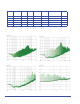
Typical radiated output at 3 meter distance (CGO-501, 505 and 515)
All values are typical values unless specifi ed.
All specifactions are subject to change without notice.
Com-Power Corporation 114 Olinda Drive, Brea California 92823 (714) 528 - 8800 www.com-power.com
5 MHz step 5 -2000 MHz
20 MHz step 20- 2000 MHz
20 MHz step 2 GHz - 5 GHz
Typical radiated output at 3 meter distance (CGO-520)
1 MHz step 1- 2000 MHz
Model Freq. range
(MHz)
Step Size
(MHz)
Internal
Battery
(NimH)
Charger
Input
(VDC)
Output
Connector
Base dimensions
dia × height
in / cm
Weight
lbs / kg
CGO-501 1-1000 1 6 V 7.5 BNC 7 × 0.75 / 17.7 ×1.9 2 /0.9
CGO-505 5-1500 5 6 V 7.5 BNC 7 ×0.75 / 17.7 ×1.9 2 /0.9
CG-515 1-1500 1 & 5 6 V 7.5 BNC 4 × 4 × 4/10 ×10 ×10* 2 /0.9
CGO-515 1-1500 1 & 5 6 V 7.5 BNC 7 ×0.75 / 17.7 ×1.9 2 /0.9
CGO-520 20-4500 20 6 V 7.5 SMA 7 ×1 / 17.7 × 2.5 2 /0.9
* For Automotive EMC Lab Recognition Program - dimensions L × W × H