
User Manual

Com-Power Corporation 114 Olinda Drive, Brea, California 92823 (714) 528 - 8800 www.com-power.com
Traditional vs
"
in-line
"
dipoles
Some manufacturers have introduced unconventional "in-
line" mini-biconical dipole antennas, in which the feed line
is along a coincident plane with, and routed through, the
center of the antenna elements, as opposed to the more
traditional dipole arrangement employed by the ABM-
6000, with the feed line perpendicular to the elements.
While the in-line arrangement does provide a more omni-
directional pattern in the H-plane (vertical axis), the E-plane
(horizontal) performance is sacrifi ced. Horizontally, the
antenna symmetry is off set by the feed line extending
out along one side of the transmit plane, forming ripples
and/or side lobes, which would not typically be present
with the traditional dipole arrangement. These anomalies
can often lead to unpredictable test results during site
validation.
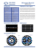
VSWR (typical)
Antenna Factors / Gain (typical)
1
2
3
4
5
6
7
8
9
10
123456
Frequency (GHz)
VSWR (x:1)
`
20
25
30
35
40
45
50
123456
Frequency (GHz)
Antenna Factor (dB/m)
-10
-5
0
5
10
15
20
Gain (dBi)
`
Specifi cations
Antenna Type Microwave Biconical
Frequency Range 1 to 6 GHz
Antenna Factor 32 to 46
dB/m
Isotropic Gain
-3 to 4.5
dBi
VSWR 3:1 (average)
3 dB beamwidth 75° to 95°
Impedance 50 ohms
Inversion Symmetry < 1 dB
Cross-polarization > 20 dB rejection
Overall Length 20.5 inches (52 cm)
Max. Width (elements) 2.5 inches (6.35 cm)
Connector Type N-type (female)
Max. Input Power 50 Watts
Weight 13 oz. (0.368 kg)
All values are typical values unless otherwise specifi ed.
Specifi cations are subject to change without notice.
Microwave Biconical
ABM-6000
Antenna Patterns (typical)
90
75
60
45
30
15
0
-15
-30
-45
-60
-75
-90
-105
-120
-135
-150
-165
180
165
150
135
120
105
90
75
60
45
30
15
0
-15
-30
-45
-60
-75
-90
-105
-120
-135
-150
-165
180
165
150
135
120
105
1 GHz
2 GHz
3 GHz
4 GHz
5 GHz
6 GHz
E-plane
H-plane
(horizontal)
(vertical)