
Maintenance Instructions

10044S
Colt Canada Proprietary 3-2-47 2005-09-20
STANDARD BUFFER ASSEMBLY
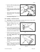
74. Repair the buffer assembly as follows:
a. Remove nicks and burrs from the buffer body with a smooth file or fine stone taking care
not to alter any original critical dimensions; and
b. Replace buffer assemblies that exhibit restriction of the interior weights and those that
bind in the receiver extension.
DISASSEMBLY
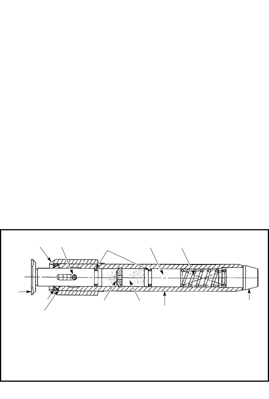
75. Disassemble the buffer assembly as follows, see figure 3-2-61:
a. Remove the riveted end of the guide and plunger retaining pin (1), and remove the pin
using a suitable pin punch;
b. Slide the assembled guide (2), and plunger (3) off of the buffer tube (4);
c. To further disassemble the guide and plunger assembly, remove the "O" ring (11) from the
plunger and slide the plunger forward out of the guide. The three piece scraper
assembly (5) and the steel retaining ring (6) can now be removed from the rear of the guide;
d. Drain the hydraulic fluid from the tube and remove the bumper (7) and piston spring (8)
to the rear;
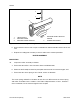
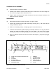
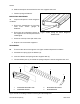
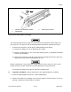
Figure 3-2-61 Hydraulic Buffer Assembly
1. GUIDE AND PLUNGER RETAINING PIN
2. GUIDE
3. PLUNGER
4. BUFFER TUBE
5. SCRAPER ASSEMBLY
6. RETAINING RING
7. BUMPER
8. PISTON SPRING
9. ORIFICE PLATE
10. REAR PISTON
11. “O” RING PACKING
12. FLUID
12
8
10
11
3
5
6
4
9
12
7