
Maintenance Instructions

10044S
Colt Canada Proprietary 3-2-42 2005-09-20
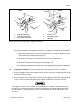
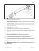
k. Torque the receiver extension nut to between 51.5 and 56.9 N
.
m (38 and 42 ft-lb); and
m. Stake the end plate securely into at least two of the receiver extension nut staking slots.
LOWER RECEIVER
64. Inspection. Inspect the lower receiver assembly as follows:
a. Inspect the lower receiver for burrs, dents, cracks and shiny surfaces;
b. Inspect the axis holes of the hinge pin and takedown pin for corrosion;
c. Gauge the hammer and trigger mechanism axis pin holes as detailed in Part 4 of this
instruction; and
d. Check the action of the pivot and takedown pin detents to ensure that they operate
effectively under positive spring tension.
65. Repair. Repair the lower receiver as follows:
a. Remove burrs with a smooth file or fine stone, taking care not to alter original critical
dimensions;
b. Touch-up shiny or reworked areas as detailed in Part 3, Section 1 of this instruction;
c. Replace defective receiver pivot pin or takedown pin components as required;
d. Disregard dents of a minor nature that do not affect operation of the weapon; and
e. Backload the weapon if the receiver is severely dented or damaged, or if the hammer or
trigger pin holes gauge beyond tolerance limits.
BUTT ASSEMBLY - SOLID BUTTSTOCK
66. The normal and short butt assemblies on the C7 or C7A1 rifles may be fitted with
buttstock extensions. When a buttstock extension is fitted to a weapon, longer screws are
required, both rifles require an extra butt plate spacer to be fitted. For the purpose of this
instruction, procedures detailed will be for butt assemblies with the buttstock extension.
67. When extensions are removed from buttstock assemblies, care must be taken to ensure
that the correct screws are used in reassembly. Care must also be taken to ensure that when
the short butt assembly is reassembled, the short butt plate screw is used. If the standard butt
plate screw is used the buffer assembly will impact on it during recoil. Refer to table in
Figure 3-2-64 to determine the correct screws for each combination of buttstock and extension.
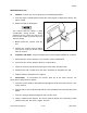
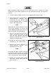
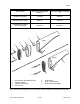
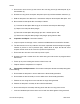
68. Removal and Disassembly. Unscrew the buttsock securing screw (1) and remove the
buttsock assembly from the rifle, see Figure 3-2-56. Further disassemble the buttstock assembly
by the following procedure: