
Maintenance Instructions
10044S
Colt Canada Proprietary 3-2-35 2005-09-20
(iv) If required for replacement, carefully remove the trigger spring (4) from the trigger (5).
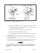
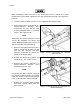
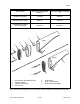
(4) To disassemble the burst trigger mechanism, see Figure 3-2-48 and proceed as follows:
(i) Apply downward pressure on the semi disconnect (1) and burst disconnect (2) to
take control of the disconnect springs (3);
(ii) Remove the slave pin (2) and release pressure on the disconnects;
(iii) Remove the disconnects and disconnect springs; and
(iv) If required for replacement, carefully remove the trigger spring (4) from the trigger (5).
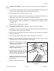
53. Inspection and Repair. Inspect and repair the fire control mechanism as follows:
a. Inspect all trigger mechanism components for cracks, corrosion, and damage that would
effect mechanism function;
b. Ensure that the three hammer bent surfaces of the trigger, disconnector, and automatic
sear are sharp, well defined and that the original contours have not been altered;
The trigger assembly for the carbine is assembled with a different disconnector spring
than the rifle. The spring used for the carbine semi disconnect is colour coded red or black
for identification. The springs for the rifle semi disconnect and all burst disconnects are
the same.
Figure 3-2-48 Disassembling the Trigger Mechanism
1. SEMI DISCONNECT
2. BURST DISCONNECT
3. DISCONNECT SPRING
4. SLAVE PIN
5. TRIGGER SPRING
6. TRIGGER
1
1
AUTO BURST
6
6
5
5
4
4
2
3
3