
Maintenance Instructions
10044S
Colt Canada Proprietary 3-2-18 2005-09-20
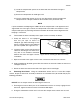
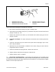
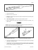
(2) Install the upper RAS segment with the front locking clamp under the handguard cap;
(3) Remove the rear clamping screw and position the clamp over the gas tube and into
the flange of the barrel nut;
(4) Pull downward on the handguard slip ring and position the flange of the upper RAS
segment under the lip of the slip ring.
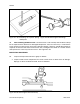
(5) When the RAS is correctly positioned tighten the clamping screw to secure the rear
of the RAS;
(6) Slide the top hand protector back in place on the RAS;
(7) Repeat for the lower RAS segment; and
(8) Slide the bottom hand protector back onto the RAS.
NOTE
All current configurations of weapons in the C7 Family utilize an attached sight either iron
or optical. Repair procedures for these sights are located near the end of Section 3.
Repair procedures for the original integral C7 iron sight will be found in those procedures.
DISASSEMBLING THE UPPER RECEIVER ASSEMBLY
17. With the barrel assembly and upper receiver assembly separated the upper receiver
assembly may be further disassembled for inspection and repair by sub-assemblies.
FORWARD ASSIST ASSEMBLY
18. Removal. Remove the forward assist assembly from the upper receiver by the following
procedure:
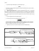
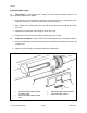
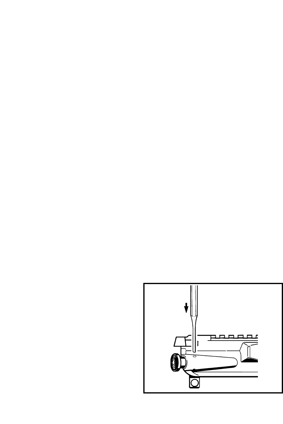
a. Drive out the forward assist assembly
pin using a suitable punch. See
Figure 3-2-24;
b. Maintaining forward pressure on the
forward assist plunger cap, remove the
punch; and
c. Carefully release the pressure on the
forward assist plunger cap then remove
the forward assist assembly and
forward assist plunger spring from the
upper receiver.
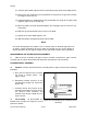
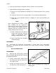
19. Disassembly. To disassemble the
forward assist assembly see Figure 3-2-25 and
proceed as follows:
Figure 3-2-24 Removing the Forward Assist
Assembly