0044S MAINTENANCE INSTRUCTIONS C7 FAMILY OF COMBAT WEAPONS 2005-0 09-2 20 COLT CANADA 1036 Wilson Avenue, Kitchener, Ontario, Canada, N2C 1J3 Tel: +1 519 893 6840 Fax: +1 519 893 3144 WWW.COLTCANADA.COM © 2005 Colt Canada Technical Publications & I.L.S (Integrated Logistic Support) - Do not reproduce in whole or in part without permission.
10044S TABLE OF CONTENTS PAGE PART 1 - INTRODUCTION . . . . . . . . . . . . . . . . . . . . . . . . . . . . . . . . . . . . . . . . . . . . 1-1-1/1-1-2 Section 1 - General Information . . . . . . . . . . . . . . . . . . . . . . . . . . . . . . . . . . . . . . . . 1-1-1/1-1-2 Purpose . . . . . . . . . . . . . . . . . . . . . . . . . . . . . . . . . . . . . . . . . . . . . . . . . . . . . . . . . . . 1-1-1/1-1-2 Scope . . . . . . . . . . . . . . . . . . . . . . . . . . . . . . . . . . . . . . . . . . . . . .
10044S TABLE OF CONTENTS (Cont) PAGE Disassembling the Upper Receiver Assembly . . . . . . . . . . . . . . . . . . . . . . . . . . . . . . . . . Forward Assist Assembly . . . . . . . . . . . . . . . . . . . . . . . . . . . . . . . . . . . . . . . . . . . . . . . . . Ejection Port Cover . . . . . . . . . . . . . . . . . . . . . . . . . . . . . . . . . . . . . . . . . . . . . . . . . . . . . . Cocking Handle . . . . . . . . . . . . . . . . . . . . . . . . . . . . . . . . . . . . . . . . . . . . . . . . . . .
10044S TABLE OF CONTENTS (Cont) PAGE PLASTIC MAGAZINE . . . . . . . . . . . . . . . . . . . . . . . . . . . . . . . . . . . . . . . . . . . . . . . . . . . . 3-2-51 Disassembly . . . . . . . . . . . . . . . . . . . . . . . . . . . . . . . . . . . . . . . . . . . . . . . . . . . . . . . . . . . 3-2-51 Inspection and Repair . . . . . . . . . . . . . . . . . . . . . . . . . . . . . . . . . . . . . . . . . . . . . . . . . . . . 3-2-51 Reassembly . . . . . . . . . . . . . . . . . . . . . . . . . . . . . . . . .
10044S LIST OF FIGURES FIGURE 2-1 3-1-1 3-2-1 3-2-2 3-2-3 3-2-4 3-2-5 3-2-6 3-2-7 3-2-8 3-2-9 3-2-10 3-2-11 3-2-12 3-2-13 3-2-14 3-2-15 3-2-16 3-2-17 3-2-18 3-2-19 3-2-20 3-2-21 3-2-22 3-2-23 3-2-24 3-2-25 3-2-26 3-2-27 3-2-28 3-2-29 3-2-30 3-2-31 3-2-32 3-2-33 3-2-34 3-2-35 3-2-36 3-2-37 3-2-38 3-2-39 3-2-40 3-2-41 3-2-42 3-2-43 TITLE PAGE Tools and Gauges . . . . . . . . . . . . . . . . . . . . . . . . . . . . . . . . . . . . . . . . . . . . . . 2-1/2-2 Torque Limits . . . . . . . . . . . . . . . . .
10044S LIST OF FIGURES (Cont) FIGURE 3-2-44 3-2-45 3-2-46 3-2-47 3-2-48 3-2-49 3-2-50 3-2-51 3-2-52 3-2-53 3-2-54 3-2-55 3-2-56 3-2-57 3-2-58 3-2-59 3-2-60 3-2-61 3-2-62 3-2-63 3-2-64 3-2-65 3-2-66 3-2-67 3-2-68 3-2-69 4-1 4-2 4-3 4-4 4-5 4-6 4-7 TITLE PAGE Removing the Trigger Guard Pivot Pin . . . . . . . . . . . . . . . . . . . . . . . . . . . . . . 3-2-32 Removing the Automatic Sear . . . . . . . . . . . . . . . . . . . . . . . . . . . . . . . . . . . . . 3-2-33 Removing the Hammer Pin . . . . . . .
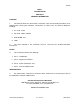
10044S PART 1 INTRODUCTION SECTION 1 GENERAL INFORMATION PURPOSE 1. This Manual details the disassembly, inspection, repair and assembly procedures to be followed when carrying out inspection, maintenance, or repair of the C7 Family of Weapons, including: a. C7, C7A1, C7A2; b. C8, C8A1, C8A2, C8CQB; c. SFW, SFSW; and d. LSW. 2. The tasks detailed in this instruction shall be carried out by Qualified Weapons Technicians. SCOPE 3. This instruction contains the following: a. Part 1 - Introduction; c.
10044S SECTION 2 C7 FAMILY TECHNICAL SPECIFICATIONS TABLE OF SPECIFICATIONS C7 C7A1 C7A2 C8 C8A1 C8A2 SFW SFSW C8CQB LSW TOTAL LENGTH (m) 1.0 1.0 1.0 Ex. 0.915 Col. * 4 pos .76, & .84 .76, & .84 .76, & .84 .78, & .85, & .88 .78, & .85 & .88 0.67 & 0.75 1.0 BARREL LENGTH(m) .51 .51 .51 .37 .37 .37 .41 .41 .25 .51 WEIGHT unloaded without accessories (kg) 3.34 3.23 3.23 2.68 2.68 2.68 3.4 3.4 2.68 5.
10044S TABLE OF SPECIFICATIONS (Cont) C7 C7A1 C7A2 C8 C8A1 C8A2 SFW SFSW C8CQB LSW REAR SIGHT TYPE Flip Type Two Aperture Flip Type Two Aperture Flip Type Two Aperture Flip Type Two Aperture Flip Type Two Aperture Flip Type Two Aperture Flip Type Two Aperture Flip Type Two Aperture Flip Type Two Aperture Flip Type Two Aperture FRONT SIGHT TYPE ROUND POST ROUND POST ROUND POST ROUND POST ROUND POST ROUND POST ROUND POST ROUND POST ROUND POST ROUND POST SIGHT RADIUS (Iron Sigh
10044S PART 2 APPARATUS AND TOOLS GENERAL 1. Tools and gauges listed in Figure 2-1 are required by the technician to perform various stages of stripping, assembling, replacement of broken or damaged parts, testing and adjusting of the C7 Family of Weapons. ITEM No. 18 19 8 13 12 16 7 4 15 5 6 2 17 3 14 11 10 9 1 Part No.
10044S PART 3 REPAIR TECHNIQUES SECTION 1 REPAIR INFORMATION GENERAL 1. DO NOT attempt to disassemble or repair those parts of the C7 Family of Weapons that are not specifically detailed in this instruction. 2. Unless otherwise specified all pins are normally removed from left to right and reassembled in the reverse direction. DO NOT disassemble items or assemblies secured by spring tension pins except to repair or replace non-serviceable components. DO NOT reuse spring tension and roll pins.
10044S SECTION 2 REPAIR PROCEDURES INTRODUCTION 1. Repair procedures detailed in this instruction apply to the C7 Family of Weapons. Where the procedures applicable to specific models differ from those specified for the rifle, the differences are detailed in a “NOTE” or described more completely in a separate paragraph. 2. Disassembly, inspection, repair and assembly procedures are detailed under the following headings: a. Safety Precautions; b. Rifles and Carbine; c.
10044S c. Danger of cook-off exists after firing more than 120 rounds in rapid succession. If the rifle stops firing with a live round in the chamber: remove unfired the cartridge immediately (within 5 seconds), or wait 2 minutes to allow the cook-off period to pass. d. DO NOT fire the rifle if there is water or other foreign material in the barrel. Firing the weapon with a bore obstruction may cause a breech or bore explosion. e. If you notice a difference in sound or recoil, STOP FIRING.
10044S 2 1 1. 2. 3. COCKING HANDLE EJECTION OPENING 3 CHAMBER AREA AND INTERIOR OF THE RECEIVER Figure 3-2-2 Proving the Weapon COMPLETE WEAPON DISASSEMBLY INTO MAJOR GROUPS 5. With the weapon cocked and the fire control selector set to the “S” position, disassemble the weapon into major groups by the following procedure: a. Loosen the wing-nut(s) on Optical Sight, Detachable Iron Sight (DIS), or Back Up Sight, and remove the sight from the sight rail.
10044S b. Push the takedown pin all the way to the right and pivot the upper receiver upward. See Figure 3-2-4; TAKEDOWN PIN c. Pull the cocking handle rearward approximately 8 cm (3 in.) to withdraw the bolt carrier group. See Figure 3-2-5; d. Remove the bolt carrier group; e. Remove the cocking handle by pulling it rearward until its guide lugs drop down out of the guideways. See Figure 3-2-6. f. Push the receiver pivot pin all the way to the right.
10044S Figure 3-2-7 Separating the Receivers j. Figure 3-2-8 Releasing the Buffer Assembly Allow part of the buffer assembly to move forward past the buffer retainer; k. Depress the hammer slightly to create sufficient clearance for the buffer assembly to pass; and m. Carefully remove the buffer assembly and return spring. REASSEMBLY OF MAJOR GROUPS 6.
10044S f. Pull the bolt fully forward in the bolt carrier and position the bolt carrier group below the cocking handle with the bolt carrier key in the cocking handle slot; g. Push the bolt carrier group and cocking handle forward until the cocking handle latches on the upper receiver; h. Align the receiver pivot pin holes in the upper and lower receiver and push the pivot pin fully to the left; and j. Carefully close the receivers and push the takedown pin fully to the left.
10044S 4 3 2 3 1 3 1. 2. 3. 4. RETAINING CLIP BOTTOM HAND PROTECTOR CLAMPING SCREW TOP HAND PROTECTOR Figure 3-2-10 RAS (4) Pull the handguard slip ring to the rear; rotate the rear of the lower RAS down; and remove it; and (5) Pull the slip ring to the rear; rotate the rear of the upper RAS up; and remove it. c.
10044S NOTE Removal of the gas tube may be difficult due to the buildup of carbon between the tube and front sight or upper receiver. To remove, grip the gas tube lightly with a pair of vise grips, being careful not to damage or restrict the tube, and tap it lightly to the rear with a small hammer. Figure 3-2-11 Removing the Gas Tube Pin (2) Slide the gas tube rearward into the receiver (1); rotate it slightly and raise the front end (2); and pull forward to remove it (3). See Figure 3-2-12. e.
10044S 3 1 2 1. 2. 3. GAS PIN TUBE TAPERED PIN FRONT SIGHT Figure 3-2-13 Removing the LSW Gas Tube DO NOT clamp the front sight or upper receiver assembly at any point during removal or disassembly of the barrel assembly, as damage or misalignment of these components may result. (1) Clamp the barrel in a vise equipped with vise jaw caps to ensure an adequate grip without damage to the barrel; and DO NOT use a torque wrench for loosening the barrel nut.
10044S Figure 3-2-15 Separating the Barrel and Upper Receiver Assemblies Figure 3-2-14 Unscrewing the Barrel Nut DISASSEMBLING THE BARREL ASSEMBLY 8. With the barrel assembly and upper receiver assembly separated, the barrel assembly may be further disassembled by the following procedures: a.
10044S (1) Remove the handguard snap ring (3) with a suitable pair of snap ring pliers; and (2) Remove the handguard slip ring spring (2) and the handguard slip ring (1) from the barrel nut. NOTE DO NOT attempt to disassemble the barrel nut from the barrel assembly. Figure 3-2-17 Removing the Compensator and Compensator Spacer INSPECTING THE BARREL ASSEMBLY 9. Inspect the components as follows: barrel assembly a. Handguards. Ensure that the handguards are not cracked or deformed.
10044S c. Gas Tube. Ensure that the gas tube is free of deformation, cracks and carbon deposits; d. Compensator. The compensator shall be free of burrs, cracks or dents. Check the compensator spacer to ensure that the laminations are uniform with no protruding sharp edges which could present an injury hazard; e. Front Sight. Ensure that the front sight post is not burred or distorted. Check the spring to ensure that it is not kinked or corroded. Check the detent for correct form and function; f.
10044S c. Compensator. Remove nicks or burrs by stoning and touch up affected areas with gun blue. Replace defective compensators. d. Front Sight. Replace defective components as required. e. Barrel Nut Assembly Components. Replace defective handguard slip rings, slip ring springs or handguard snap rings as required. Backload the weapon for replacement of a defective barrel nut. f. Front Sling Swivel.
10044S (vi) Touch-up the damaged surface finish as detailed in Part 3, Section 1 of this instruction. (4) Remove carbon from the gas tube hole of the front sight using a 5.56 mm bore brush; (5) Replace loose or missing barrel indexing pins; and (6) Replace barrel assemblies that have defective barrels. REASSEMBLING THE BARREL ASSEMBLY 11.
10044S (1) Install the compensator spacer on the barrel with the laminations facing the compensator; (2) Screw the compensator on hand tight; and (3) Use the combination wrench and a 1/2 inch drive torque wrench to tighten the compensator to a torque of between 62.4 and 69.1 N·m (46 and 51 ft-lb).
10044S c. Repeat the above, torquing the nut a total of three times. NOTE The multiple torquing procedure provides for a better thread fit and ensures that the barrel nut will not work loose. 14. Rebreeching Existing Barrel. Using the combination wrench and a 1/2 inch drive torque wrench, torque the barrel nut assembly to between 41 and 108.5 N.m (30 and 80 ft-lb), ensuring that all three drive pins of the combination wrench are evenly engaged in the barrel nut. 15.
10044S NOTE The barrel nut is correctly installed and aligned when the alignment tool passes freely through the assembly and is centred over the barrel. 16. Finish reassembly of the upper receiver and barrel group by installing the gas tube and handguard assemblies by the following procedures: a.
10044S (2) Install the upper RAS segment with the front locking clamp under the handguard cap; (3) Remove the rear clamping screw and position the clamp over the gas tube and into the flange of the barrel nut; (4) Pull downward on the handguard slip ring and position the flange of the upper RAS segment under the lip of the slip ring.
10044S 5 1 4 2 3 1. 2. 3. FORWARD ASSIST PAWL FORWARD ASSIST DETENT FORWARD ASSIST DETENT SPRING 4. 5. FORWARD ASSIST PAWL PIN FORWARD ASSIST PLUNGER ASSEMBLY Figure 3-2-25 Disassembling the Forward Assist Assembly a. Drive out the forward assist pawl pin (4) with a suitable punch; b. Take control of the forward assist pawl (1) and remove the punch from the forward assist plunger assembly (5); and c. Remove the forward assist detent (2) and forward assist detent spring (3) from the plunger assembly.
10044S EJECTION PORT COVER 22. Disassembly. To disassemble the ejection port cover from the upper receiver, see Figure 3-2-26 and proceed as follows: a. Using the tips of two small punches or flat tip screwdrivers remove the ejection port cover hinge pin snap ring (1) from the ejection port cover hinge pin (2); b. Take control of the ejection port cover (4) and ejection port cover spring (3) to prevent their loss; c. Remove the ejection port cover hinge pin to the rear; and d.
10044S 24. Reassembly. Install the ejection port cover and apply tension to the cover spring by the following procedure: a. Position the cover and spring on the upper receiver, with the short spring leg against the upper receiver, at the rear of the spring housing and pointing upward; b. Insert the hinge pin through the rear axis lug on the receiver, through the rear hinge section of the ejection port cover, and midway into the spring; c.
10044S b. Touch up affected areas as detailed in Part 3, Section 1 of this instruction; c. Repair distorted carrying handles as follows: (1) Remove rear sight components if damage may result during repairs to the carrying handle; (2) Clamp the receiver, by the carrying handle, in a vise fitted with protected jaws; (3) Using two 6 inch adjustable wrenches, straighten the bent carrying handle.
10044S Figure 3-2-29 Removing the Firing Pin c. Push the bolt rearward; d. Rotate the cam pin 1/4 turn; and e. Withdraw the cam pin from the bolt carrier group and pull the bolt out of the bolt carrier. See Figure 3-2-30. 30. Disassembling the Bolt. The bolt may be disassembled as follows: a. Using a suitable punch, push out the extractor pin and remove the extractor. See Figure 3-2-31; DO NOT attempt to remove the extractor spring and spring insert from the extractor.
10044S Figure 3-2-32 Removing the Ejector Spring Figure 3-2-33 Removing the Bolt Rings and Ejector 43. Disassembling the Bolt Carrier. The bolt carrier is not normally disassembled, except for the replacement of defective or damaged components, since the carrier key is sealed to the carrier and the securing screws are heavily staked in position.
10044S b. Visually inspect the bolt rings for bends, kinks or breaks. If one or more of the rings are damaged, replace all three rings; c. Visually inspect the bolt carrier key screws for looseness and security of the staking. If the bolt carrier key screws are found to be loose, retorque them to 5.54 to 5.88 N.m (35 to 40 in-lb) and restake; and NOTE DO NOT attempt to retorque if there is no loosening of the screws indicated at the staking marks. d. Replace non-serviceable components as required.
10044S c. To install the extractor, hold the extractor and spring in position, see Figure 3-2-36 and insert the extractor pin. 34. Reassemble the key to the bolt carrier as follows: a. Clean the mating surfaces of the bolt carrier key, and bolt carrier, thoroughly; b. Apply a light layer of sealing compound, to the under surface of the bolt carrier key around the gas port, to form a seal; Apply the sealing compound sparingly and only to the area immediately surrounding the gas porthole.
10044S b. Rotate the bolt to position the extractor on the right and insert the cam pin into the bolt; NOTE The cam pin hole in the bolt is swaged so that the cam pin can only be inserted from one direction. This is to prevent the bolt from being assembled with the extractor in the wrong position. c. Rotate the cam pin 1/4 turn either way; d. Pull the bolt forward; e. Insert the firing pin into the bolt and push it fully forward; and f.
10044S NOTE The takedown pin detent and spring are retained in the lower receiver by the butt. Take care to ensure that neither of these parts is lost or damaged during disassembly/assembly procedures. b. Cover the lower half of the lower receiver assembly and butt assembly where the two meet, to prevent loss of the takedown pin detent (4) and takedown pin detent spring (3); c. Remove the butt assembly (2) rearward from the lower receiver assembly; and d.
10044S 5 4 3 2 1 1. 2. 3. 4. 5. PISTOL GRIP SCREW LOCKWASHER PISTOL GRIP SELECTOR DETENT SPRING SELECTOR DETENT Figure 3-2-39 Removing the Pistol Grip c. Remove the pistol grip, selector detent spring and selector detent (5); and d. Remove the fire control selector. 41. Inspection and Repair. components as follows: Inspect and repair the pistol grip and fire control selector a. Ensure that the grip is free of cracks, distortions and deformation; b.
10044S a. Remove the bolt catch pin with the special punch. See Figure 3-2-40; b. Apply slight pressure to the bolt catch to control spring pressure when removing the punch; and c. Carefully release pressure and remove the bolt catch (1) bolt catch plunger (2) and the bolt catch spring (3). See Figure 3-2-41. 44. Inspection and Repair. Inspect and repair the bolt catch as follows: a. Ensure that the bolt catch spring and plunger are free of wear, cracks or distortion; b.
10044S c. Replace non-serviceable components as required. 45. Reassembly. disassembly. Reassemble the bolt catch components in reverse order to the MAGAZINE CATCH 46. Removal. Remove the magazine catch as follows: a. Push the magazine release button fully into the receiver and unscrew the magazine catch. See Figure 3-2-42; b. Slowly release pressure on the magazine release button, taking control of the magazine catch spring as it is exposed; and c.
10044S b. The plate and shaft of the magazine catch shall be securely assembled; c. The magazine catch spring shall not be kinked, set or broken; and d. Replace non-serviceable components as required. 48. Reassembly. Reassemble the magazine catch to the lower receiver in reverse order to the disassembly procedure. Ensure that the end of the threaded shaft is flush or slightly below the serrated surface of the magazine release button. TRIGGER GUARD 49. Removal and Disassembly.
10044S d. Replace non-serviceable components as required. 51. Reassembly and Replacement. Reassemble the trigger guard and replace in reverse order to the disassembly procedure. Ensure that the area around the trigger pivot hole of the lower receiver is properly supported when reinstalling the trigger guard pivot pin. FIRE CONTROL MECHANISM 52. Disassembly. The fire control mechanism shall only be disassembled if there is excessive side play or if the mechanism malfunctions.
10044S (2) Take control of the hammer and remove the punch; (3) Remove the hammer assembly; and (4) If required for replacement, carefully remove the hammer spring from the hammer by spreading out one side at a time to prevent distortion of the spring. NOTE On C7 Family weapons capable of 3 round burst firing mode, the burst cam and clutch spring can be removed from the right boss of the hammer once the hammer spring has been removed. d. Trigger Mechanism.
10044S AUTO 1 BURST 2 3 3 1 6 6 4 4 5 5 1. 2. 3. SEMI DISCONNECT BURST DISCONNECT DISCONNECT SPRING 4. 5. 6. SLAVE PIN TRIGGER SPRING TRIGGER Figure 3-2-48 Disassembling the Trigger Mechanism (iv) If required for replacement, carefully remove the trigger spring (4) from the trigger (5).
10044S c. Check the springs both helical and torsion, for kinks, cracks or distortion; d. Check for sticking or drag between the hammer and disconnector. Polish the mating surfaces to correct the problem; e. Ensure that the trigger mechanism passes all safety, function, and trigger pull criteria detailed in Part 4 of this instruction; and f. Replace non-serviceable parts as required. 54. Reassembly and Replacement. Reassemble the fire control mechanism and replace it in the receiver as follows: a.
10044S RECEIVER PIVOT PIN 55. Removal. Remove the receiver pivot pin by the following procedure: a. Insert the end of a suitable punch into the hole in the pivot pin, to depress the detent. See Figure 3-2-50; b. Rotate the pivot pin 90 degrees; The receiver pivot pin detent is under considerable spring tension. Before removing the pin, cover the front of the receiver, with a cloth, to prevent loss of the detent or spring. c. Slowly remove the receiver pivot pin; and d.
10044S B A Figure 3-2-51 Replacing the Receiver Pivot Pin e. Rotate the tool and punch 90 degrees. f. Hold the pivot pin, with the groove outward, firmly against the end of the assembly tool; g. Push the pivot pin into the right receiver lug; and h. Rotate the pin 180 degrees and allow the detent to take up its position in the groove of the pivot pin. See Figure 3-2-51B; RECEIVER EXTENSION - SOLID BUTTSTOCK 58. Removal.
10044S Figure 3-2-52 Unscrewing the Receiver Extension c. Remove the buffer retainer, buffer retainer spring, takedown pin detent spring, takedown pin detent and the takedown pin. 59. Inspection and Repair. Inspect the receiver extension to ensure that it is free of cracks, dents or other deformation which would impede the return spring or the buffer assembly. Replace a defective extension. 60. Reassembly. Proceed as follows: a.
10044S When clamping the lower receiver in a vise, ensure that the vise is closed over a solid portion of the receiver body. Tighten the vise only sufficiently to provide a firm grip on the receiver. a. Carefully clamp the lower receiver in a vise equipped with protected jaws; b. Unscrew the receiver extension nut, in a counter-clockwise direction, when viewed from the rear, with the hook wrench (CF62420) and a 1/2 inch drive ratchet.
10044S 62. Inspection and Repair. follows: Inspect and repair the receiver extension components as a. Inspect the receiver extension for dents, cracks and other deformation that would impede the action of the sliding buttstock, buffer assembly, or return spring; b. Ensure that the receiver extension vent hole is clear; c. Check the receiver end plate and receiver extension nut for cracks or deformation that would affect security of the receiver extension or takedown pin detent; d.
10044S k. Torque the receiver extension nut to between 51.5 and 56.9 N.m (38 and 42 ft-lb); and m. Stake the end plate securely into at least two of the receiver extension nut staking slots. LOWER RECEIVER 64. Inspection. Inspect the lower receiver assembly as follows: a. Inspect the lower receiver for burrs, dents, cracks and shiny surfaces; b. Inspect the axis holes of the hinge pin and takedown pin for corrosion; c.
10044S APPLICATION BUTTSTOCK SECURRING SCREW (1) BUTTSTOCK SWIVEL SCREW (2) SHORT BUTTSTOCK CF64540 CF64573 STANDARD BUTTSTOCK 8690174-1 CF64573 STANDARD BUTTSTOCK WITH EXTENSION 8690174-2 8890076-1 5 6 LONG 7 6 4 1 3 2 SHORT 5 3 1 4 2 1. 2. 3. 4. 5. 6. 7.
10044S a. Unscrew the swivel screw (2) that secures the rear sling swivel (3) and butt plate (4) to the buttstock (5); b. Remove the sling swivel, butt plate, butt plate spacer (6) and the buttstock extension (7); c. Hold the butt plate face down over a work bench and push the butt plate door open; and d.
10044S g. Insert the detent and spring into the hole in the rear of the lower receiver. See Figure 3-2-57; h. Replace the butt assembly ensuring that the spring does not kink, but that it is compressed into the hole in the lower receiver; j. Hold the butt in position while replacing the butt plate spacer, and buttstock extension; and k. Secure the buttstock to the weapon with Figure 3-2-57 Replacing the Butt Assembly the buttstock securing screw. BUTT ASSEMBLY - SLIDING BUTTSTOCK 71. Disassembly.
10044S 3 4 5 2 1 1. 2. 3. 4. LOCK PIN NUT RELEASE LEVER RELEASE LEVER LOCK PIN 5. RELEASE LEVER LOCK PIN SPRING SLIDING BUTTSTOCK Figure 3-2-60 Disassembling the Sliding Butt Assembly b. Ensure that the release lever nut pin is installed flush with the outside surfaces of the nut; and c. Replace the sliding butt assembly in reverse order to the removal procedure. BUFFER ASSEMBLY INSPECTION 73. Inspect the buffer assembly as follows: a.
10044S STANDARD BUFFER ASSEMBLY 74. Repair the buffer assembly as follows: a. Remove nicks and burrs from the buffer body with a smooth file or fine stone taking care not to alter any original critical dimensions; and b. Replace buffer assemblies that exhibit restriction of the interior weights and those that bind in the receiver extension. DISASSEMBLY 75. Disassemble the buffer assembly as follows, see figure 3-2-61: a.
10044S NOTE The bumper is normally damaged during removal and is not reused. e. Carefully position a 0.092 in. (2.3 mm) pin punch through the hole in the orifice plate (9) and push out the rear piston (10). Remove the "O" ring from the piston. NOTE DO NOT move the orifice plate (9) or scratch the inside of the buffer tube with the punch. Tubes with damaged cylinders or orifice plates, are not repairable. REPAIR 76.
10044S e. Place the bumper (7) in the tube and carefully press it into place; f. Carefully clamp the assembly upright in a vice and fill the tube to the level of the guide and plunger retaining pin hole with approximately 3.5 cc of hydraulic fluid MIL-H-5606 (NATO H-515) or equivalent; g.
10044S d. Slide the baseplate rearward and clear of the magazine box; and e. Remove spring and follower. INSPECTION AND REPAIR 79. Inspect and repair the metal magazine as follows: a. Ensure the components are free from nicks, burrs, cracks, gouges or distortion; b. Ensure the lips and locking surfaces of Figure 3-2-62 Lifting the Metal Magazine the magazines are correctly formed and Bottom Plate undamaged; c. Check the security of the spot welds; and d. Replace non-serviceable magazines. REASSEMBLY 80.
10044S d. Slide the baseplate into position and ensure that the baseplate engages the lugs on the box. PLASTIC MAGAZINE DISASSEMBLY 81. To disassemble the plastic magazine see figure 3-2-64 and proceed as follows: a. Take control of the baseplate (1) to control the spring; and 2 3 4 1 5 1. 2. 3. 4. 5. MAGAZINE BASEPLATE MAGAZINE BODY BASEPLATE TAB MAGAZINE SPRING MAGAZINE FOLLOWER Figure 3-2-64 Assembling and Disassembling the Plastic Magazine b.
10044S c. Replace non-serviceable magazines. REASSEMBLY 83. To reassemble the plastic magazine proceed as follows: a. Assemble the spring to the follower; b. Insert the follower and spring into the magazine body; c. Position baseplate on spring and compress the spring into the magazine body; d. Hook the baseplate into the slot at the rear of the body; and e. Rotate the front of the baseplate up to engage the body of the magazine. SIGHTS IRON SIGHT 84. Disassembly.
10044S 3 2 1 1. 2. 3. REAR SIGHT WINDAGE SCREW REAR SIGHT REAR SIGHT SPRING Figure 3-2-67 Removing the Rear Sight The clamping shafts of these sights are staked to prevent inadvertent removal and loss of the wing nuts. The wing nuts are not normally removed except for replacement of parts. f.
10044S VICE 4 1. 2. CUT LINE 1 2 3 3. 4. CLAMPING SHAFT CLAMPING PLATE SPRING WASHER WING NUT Figure 3-2-68 Removing the Wing Nuts from the DIS c. Remove nicks and burrs with a smooth file or fine stone, taking care not to alter original critical dimensions; and d. Replace non-serviceable parts as required. 86. Reassembly. Reassemble the sight in reverse order to the disassembly procedure. Stake the clamping shafts to secure the wing nuts as follows: a.
10044S b. Ensure that the front sight protectors are not bent or cracked, and that the front sight post is secure; c. Inspect the barrel to ensure that it is straight, free from fouling or other obstruction, and meets gauging requirements. Rifles which show evidence of erosion at the commencement of rifling (C of R) should be range tested for accuracy and incidents of keyholing; d. Ensure that the chamber is free of roughness or burrs, and that the chromium plating is intact; e.
10044S PART 4 TESTS AND ADJUSTMENTS FIRING PIN PROTRUSION 1. Test firing pin protrusion as follows: a. Disassemble the firing pin and bolt from the bolt carrier; b. Thoroughly clean the firing pin, bolt and firing pin protrusion gauge; c. Insert the firing pin into the bolt from the rear and hold it fully forward; and d. Gauge firing pin protrusion. See Figure 4-1. 2. Should the firing pin protrusion not meet gauging limits, that is if it is not within the 0.71 to 0.91 mm (0.028 to 0.036 in.
10044S a. Break open the weapon and remove the bolt carrier group; b. Thoroughly clean the bore and 5.49 mm bore straightness “GO” gauge; c. Hold the weapon over a work bench with the barrel vertical; and d. Insert the gauge into the barrel from the breech end. See Figure 4-3. NOTE DO NOT allow the gauge to fall onto a hard surface. 6. The gauge shall pass freely through the barrel. Clean and retest weapons failing to pass the gauge freely. a.
10044S 3 2 1 1. 2. HEADSPACE DIMENSION CARTRIDGE SEAT OF BOLT 3. DATUM DIAMETER OF CHAMBER CONE Figure 4-4 Headspace Dimension Detail Figure 4-5 Correct Indication with “NOT GO” Headspace Gauge a serviceable bolt, it is determined that the barrel assembly is non-serviceable, replace the barrel assembly. BOLT RING WEAR 9. Check for worn bolt rings as follows: a. Remove the bolt carrier group from the weapon; b. Remove the bolt from the bolt carrier; c. Thoroughly clean the bolt and bolt carrier; d.
10044S e. Move the bolt in and out to check for binding in the bolt carrier; and f. Hold the bolt carrier with the bolt facing downward. See Figure 4-6. 10. The bolt shall not drop out of the bolt carrier on its own weight. If the bolt drops out, replace all three bolt rings. RETURN SPRING LENGTH 11. See Table of Specifications approximate return spring lengths. for 12. Replace Defective Springs. DO NOT attempt to adjust spring length by stretching the Figure 4-6 Bolt Ring Wear Test spring.
10044S TRIGGER MECHANISM SAFETY TEST 16. Test the function and safety of the trigger mechanism as follows: a. With the fire control selector set at “S”: (1) Remove the magazine; (2) Clear the chamber; (3) Open the receivers; and (4) Depress the trigger: the hammer shall not move forward. b.
10044S ZEROING IRON SIGHTS 17. General. Zeroing the rifle is accomplished through adjustments to both the front sight and the rear sight. See Figure 4-7. Detachable Iron Sight Back-up Sight Front Sight Figure 4-7 Sight Adjustment 18. Adjusting the Rear Sight. The sight on the DIS and Back-up sights has two aperatures. The large aperature (battle sight) is used for shooting at short range or during low light conditions. The small aperature can be used at all ranges.