
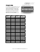
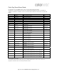
Specifications

Install Fixture
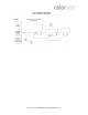
1. Electrical Connection
Connect field supply wires (120VAC or 24DC—see specifications) to driver input power leads using appropriately sized wire nuts.
Hot to black, neutral to white, ground to green and bare copper wire (if applicable).
2. Data Connection
Connect data cables in series.
Note: Fixtures on a serial data link must be daisy chained in one single line. To comply with the EIA-485 standard, no more
than 32 fixtures should be connected on one data link. Connecting more than 32 fixtures on one serial data link without the
use of a DMX optically-isolated splitter may result in deterioration of the digital DMX signal.
Maximum recommended serial data link distance: 500 m (1640 ft)
Maximum recommended number of fixtures on a serial data link: 32
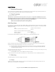
DMX Data Cable
If installer prefers 3-wire data cables, we suggest a Belden© 9481 or equivalent cable which meets the specifications for EIA RS-
485 applications. Standard microphone cables cannot transmit DMX data reliably over long distances. The cable must have the
following characteristics:
Type: shielded, 2-conductor twisted pair
Maximum capacitance between conductors:
30 pF/ft
Maximum capacitance between conductor and shield:
55 pF/ft
Maximum resistance: 20 ohms/1000 ft
Normal impedance: 100∼140 ohms
If installer prefers a RJ45/CAT5 Data installation, a RJ45 jack can be used (use PCL004 RJ45 coupler).
Note: To comply with all local codes and jurisdiction, qualified communications technicians must do communications wiring.
Note: Communication cables and AC power lines must not be run in the same conduit.
A. Route Data Cables in series between housing and any communications accessories using DATA IN and DATA OUT.
B. In order that they may be easily accessed from the room once construction is complete, secure data cables in the
immediate proximity of the housings.
Coloronix strongly recommends clearly marking communication cables near the RJ45 connectors (or end of cables) in such a way
to indicate the correct order of connection.
C. Use RJ45 DMX terminator, insert in “DATA OUT” of last fixture in series.
Note: To avoid signal transmission problems and interference, it is always advisable to connect to a DMX signal terminator.
3. Mounting
Attach Mounting Place to junction box using (2) screws provided.
4. Cover
Position cover at ceiling and tighten side screw. Finial must be securely tightened to maintain proper grounding of the cover.
Tighten finial by hand. Use gloves to avoid fingerprints.
Page 10—Coloronix RGBW Pendant Lighting Manual V1.0