
Installation guide


66840/035-20003-001Rev.B(1205)
SECTION IV: GAS PIPING
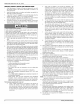
GAS SAFETY
kDANGER
This furnace is designed to operate on NATURAL GAS or PRO-
PANE GAS ONLX Do not burn any other fuel in this furnace. Bum-
ing any fuel except NATURAL GAS or PROPANE GAS can cause
premature heat exchanger burnout, high levels of carbon monox-
ide, excessive sooting, a fire hazard, personal injury, property dam-
age and/or death.
An overpressure protection device, such as a pressure regulator,
must be installed in the gas piping system upstream of the furnace
and must act to limit the downstream pressure to the gas valve so it
does not exceed 0.5 PSI (14" w.c. (3.48 kPa)). Pressures exceed-
ing 0.5 PSI (14" w.c. (3.48 kPa)) at the gas valve will cause damage
to the gas valve, resulting in a fire or explosion or cause damage to
the furnace or some of its components that wil! result in property
damage and loss of life.
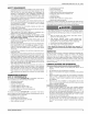
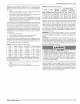
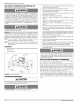
OUTLET
PRESSURE r! I_] I'_
PORT L_ I I
WRENCH _ _
BOSS __
INLET/
PRESSURE
PORT
VENT PORT
OUTLET
N REGULATOR
ADJUSTMENT
ON/OFF SWITCH
(Shown in OFF position)
FIGURE 8: Gas Valve
CHECKING THE GAS PRESSURES
1. The pressure ports on the gas valve are marked OUT P and IN
R
2. The manifold pressure must be taken at the port marked OUT R
3. The inlet gas supply pressure must be taken at the port marked
INP.
4. Using a 3/32" (0.2 cm) Allen wrench, loosen the set screw by
turning it 1 turn counter clockwise. DO NOT REMOVE THE
SET SCREW FROM THE PRESSURE PORT.
5. Push one end the 3/8" (0.9 cm) ID flexible tubing over the pres-
sure port so that the body of the port is inside the tubing.
6. Use a reducer connector to connect the 3/8" (0.9 cm) ID flexible
tube to a 1/4" (0.9 cm) ID flexible tube that is connected to a "U"
tube manometer or digital pressure measuring equipment.
TABLE 6: Inlet Gas Pressure Range
INLET GAS PRESSURE RANGE
Natural Gas Propane (LP)
Minimum 45" W.C (1 12 kPa) 80" W.C (1 99 kPa)
Maximum 105" W.C. (261 kPa) 130" (3.24 kPa) WC.
IMPORTANT: The inlet gas pressure operating range table specifies
the minimum and maximum gas line pressures required for safe fur-
nace operation.
The minimum inlet gas pressure required to obtain the BTU input
specified on the rating plate and in these instructions is shown below:
• 4.5" W.C. (1.12 kPA) for Natural Gas
• 11.0" W.C. (2.74 kPA) for Propane (LP) Gas
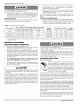
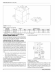
GAS
GAS _ PIPE
SHUT-OFF
VALVE
VENT --
BLOWER
DRIP
LEG --_
ROLL-OUT _
SWITCH
PRESSURE
GAS
VALVE
HOT
IGNITOR
ROLL-OUT
SWITCHES
BLOWER
DOOR
SWITCH
FURNACE
CONTROL
FIGURE 9: Upflow Configuration
GAS PIPING INSTALLATION
Properly sized wrought iron, approved flexible or steel pipe must be
used when making gas connections to the unit. If local codes allow the
use of a flexible gas appliance connection, always use a new listed con-
nector. Do not use a connector that has previously serviced another gas
appliance.
Some utility companies or local codes require pipe sizes larger than the
minimum sizes listed in these instructions and in the codes. The furnace
rating plate and the instructions in this section specify the type of gas
approved for this furnace - only use those approved gases. The instal-
lation of a drip leg and ground union is required. Refer to Figure 10.
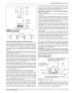
MAN UAL
SHUT-OFF
VALVE
--GAS BURNERS
-- GAS VALVE
HI....................................................................3
DRIP MANLJAL
LEG SHUT-OFF VALVE
FIGURE 10: Horizontal Gas Piping
IMPORTANT: An accessible manual shut-off valve must be installed
upstream of the furnace gas controls and within 6 feet (! .8 m) of the fur-
nace. Refer to Figures 9 and 10.
The furnace must be isolated from the gas supply piping system by
closing its individual external manual shutoff valve during any pressure
testing of the gas supply piping system at pressures equal to or less
than 1/2 psig (3.5 kPa).
CAUTION]
The gas valve body is a very thin casting that cannot take any
external pressure. Never apply a pipe wrench to the body of the gas
valve when installing piping. A wrench must be placed on the octa-
gon hub located on the gas inlet side of the valve. Placing a wrench
to the body of the gas valve wil! damage the valve causing improper
operation and/or the valve to leak.
Gas piping may be connected from either side of the furnace using any
of the gas pipe entry knockouts on both sides of the furnace. Refer to
Figure ! dimensions.
Unitary Products Group 9