
Installation guide


66840/035-20003-001Rev.B(1205)
When a furnace is installed in an attic or other insulated space,
keep all insulating materials at least 12 inches (30.5 Cm) away from
furnace and burner combustion air openings.
SUSPENDED FURNACE / CRAWL SPACE
INSTALLATION
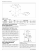
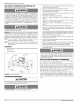
The furnace can be hung from floor joists or installed on suitable blocks
or pad. Blocks or pad installations shall provide adequate height to
ensure the unit will not be subject to water damage. Units may also be
suspended from rafters or floor joists using rods, pipe angle supports or
straps. Angle supports should be placed at the supply air end and near
the blower deck. Do not support at return air end of unit. All four sus-
pension points must be level to ensure quiet furnace operation. When
suspending the furnace, use a secure platform constructed of plywood
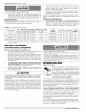
or other building material secured to the floor joists. Refer to Figure 5
for typical crawl space installation.
ANGLE IRON
BRACKET
SUPPORT
ROD
1"MAX, BETWEEN 6"MtN BETWEEN
ROD & FURNACE ROD & FURNACE
1"MAX, BETWEEN
ROD & FURNACE
FIGURE 5: Typical Suspended Furnace / Crawl Space Installation
SECTION IIh FILTERS
FILTER INSTALLATION
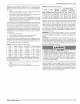
All applications require the use of a filter. Models must have a field-sup-
plied filter and mounting hardware. Replacement filter size is shown in
Table 5.
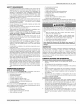
TABLE 5: Filter Sizes - Upflow
UPFLOW Side
Cabinet Return
Input Output Air Flow Size
MBH kW MBH kW CFM cmrn in. crn
75 220 60 17.6 1200 34.0 B 25x16 64x41
75 220 60 17.6 1600 45.3 C 25x16 64x41
100 293 80 23.4 1600 45.3 C 25x16 64x41
Bottom/End
Return
in. cm
24x 15 61 x38
24x 18 61 x46
24x 18 61 x46
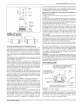
SIDE RETURN/BOTTOM EXTERNAL INSTALLATION
Locate and knock out the square corner Iocators. These indicate the
size of the cutout to be made in the furnace side panel. Refer to Figures
1 and 6.
_ FRONT OF
r
I I _ CORNER
Iq FJ J_ MARKINGS
FIGURE 6: Side Return Cutout Markings
Install the side filter rack following the instructions provided with that
accessory. If a filter(s) is provided at another location in the return air
system, the ductwork may be directly attached to the furnace side
panel. An accessory filter rack is available for mounting the filter exter-
nal to the cabinet.
Some accessories such as electronic air cleaners and pleated media
may require a larger side opening. Follow the instructions supplied with
that accessory for side opening requirements. Do not cut the opening
larger than the dimensions shown in Figure 1.
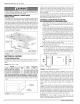
EXTERNAL FILTER INSTALLATION FOR
UPFLOW/HORIZONTAL CONFIGURATIONS
1. Select desired filter position for upfiow/horizontal (left/right side,
bottom). Remove the corresponding cabinet cut-outs per instruc-
tions provided.
2. Install the external filter box to the side of the cabinet and secure to
the cabinet as specified in the instructions provided with the air fil-
ter kit. If a side return is to be used, cut out the side of the casing
14" high by 16 1/4" wide using the lances in the casing side as a
guide. DO NOT CUT THE OPENING LARGER THAN 14" X 16 1/
4". It is not permissible to cut out the back of the furnace. For bot-
tom returns, place the external filter box between the return air ple-
num and the base of the furnace. The casing bottom is embossed
to indicate where to bend the flanges. Refer to Figure ! for the
maximum return air opening sizes. Seal this connection to prevent
leaks.
3. Install the return air duct to the air filter box and secure with
screws. Seal this connection to prevent leaks.
4. Install the field provided filter. Refer to Table 5 for the recom-
mended filter size for your furnace.
NOTE: Air velocity must not exceed 300 feet per minute through low
velocity disposable filters. Air velocity must not exceed 650 feet
per minute through high velocity cIeanable permanent filters.
Use d a filter that is too small will cause static pressure in the
duct system to be too high, which will have an adverse effect on
heating and cooling operation.
A IR__ _F
FILTER
RETURN
DUCT
[]
[]
[]
[]
MN I
[] []
[] FURNACE []
[]
[] D
[]
[]
FIGURE 7: Horizontal Mount and Filter
If the accessory electronic air cleaner is installed, be sure the air
cleaner is designed to accommodate the furnace CFM (cm/m) and the
air cleaner is installed so it does not obstruct the return airfow. Consid-
eration should be given when locating the air cleaner for maintenance
and temperatures should the indoor fan motor fail to operate. The use
of straps and / or supports is required to support the weight of the elec-
tronic air cleaner. It is recommended that the air cleaner not be located
within 12 inches (2.5 cm) from the top of the return air opening on the
furnace. Refer to the instructions supplied with the electronic air
cleaner.
If pleated media air filters or any filter that has a large pressure drop is
installed in the return air duct system be sure that the pressure drop
caused by the air filter will not prevent the furnace from operating within
the rise range specified on the rating plate. If the furnace does not oper-
ate within the specified rise range then a larger air filter or an air filter
that has a lower pressure drop must be installed. Refer to Table 16 and
the furnace accessories for accessory external filter kit options.
IMPORTANT: Air velocity through throwaway type filters must not
exceed 300 feet per minute (1.52 m/m). All velocities over this require
the use of high velocity filters. Refer to Table 16.
8 Unitary Products Group